Static Pointer Landmarks and Segments
Static Pointer Landmarks and Segments
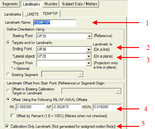
The Landmark defining the location of the Tip of a Static Pointer is done in three steps.
The first step is to use the data in the Pointer INI File to create a Landmark at the tip of the pointer relative to 3 tracking markers. It is possible to use this Landmark for determining the anatomical landmarks but it is useful to use all 6 tracking markers that are available. Visual3D uses Optimal Tracking for locating a segment in space, and it has been demonstrated in the literature that using 6 markers connected to a rigid body produces more accurate results that three markers. Additionally, Visual3D will compute the orientation of a segment using as many markers as exist in the frame (must be greater than or equal to 3 markers). Thus, if one marker is obscured the TIP Landmark can still be computed.
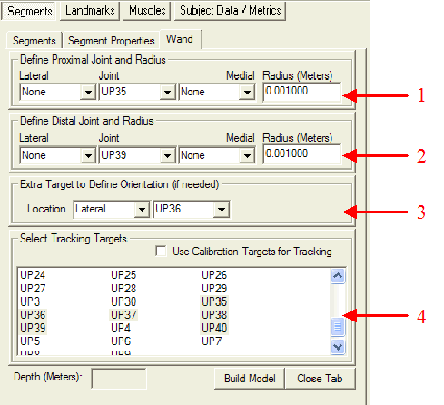
The Wand Segment is defined using the three markers associated with the temporary landmark, and tracked using all 6 tracking markers.
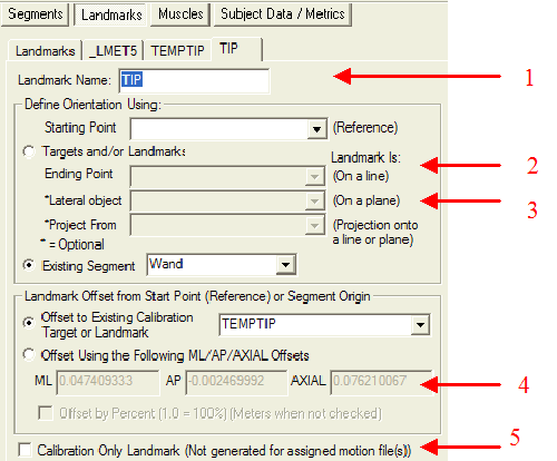
The TIP Landmark that is used for identifying the anatomical locations is then defined with respect to the location of the TEMPTIP Landmark in the Wand Segment Coordinate System.
Note: The Segment and Landmarks are created automatically when the Pointer INI file is interpreted. The information is presented here only for completeness.
Static Pointer Event Labels
Event Labels can not be computed automatically for Static Pointer because there is no trigger (e.g. the compression of the spring of the Davis Pointer) to base the Event identification on.
If the user can add a Trigger signal as an A/D channel Visual3D can use this signal to compute the Events
Typically, the user must create the Event Labels manually by looking at the travel of the Tip Landmark and setting an Event (labeled as a ?) at each location that the tip of the wand isn't moving in space. This process is not particularly time consuming and need only be done once; Exporting the Movement Trial that includes the Event Labels.


