Table of Contents
Introduction to xManager
The purpose of this tutorial is to guide you in the creation of a subject file in DSX Manager. The instructions for this tutorial are purposely designed to be general so that you can use your own data.
Subject
Create New Subject
In order to create a new subject you can either use the Ctrl + N shortcut or can select File in the menu bar and clicking on New Subject.

This will open a standard file browser window that will allow you to choose a new file name and save the New Subject file in the location of your choosing.

Complete New Subject Info
Once a new subject has been created it will appear as 0000 in the left hand field. Select the 0000 and the right hand field will be populated with the following fields:
- ID - This number or name will replace the 0000 that is found in the left hand field
- Time Precision - This is the number of decimal places used in all time values across all the DSX applications. This appears in both the graphical user interface and in the data files.
- Units - This parameter defines the units for the voxel sizes in the scan data and the pixel sizes in the x-ray data.
- First Name
- Last Name
- Study Description - There's no limit to the length of the Study Description that you can enter.

Sessions
Add Sessions
Click the arrow button to the left of the Subject ID number in the left hand field to expand the list. Left click on the Sessions Label so that the Add Sessions option appears. Click on Add Sessions.

This will cause an arrow to appear to the left of the Sessions Label. Click on the arrow in order to expand the list. It will expand to show the label newsessions, which can in turn be expanded to show the labels Objects and Configurations.

Complete Session Info
Once a new session has been created it will appear as newsession in the left hand field. Select the newsession and the right hand field will be populated with the following fields:
- Subject Parameters
- Name - This will replace the newsession label in the left hand field.
- Gender
- Age (yrs)
- Height (cm)
- Weight (kg)

The subject parameters listed above can change between sessions, so they need to be entered for each session.
- Paths
- The Paths section is displayed only when the Paths checkbox is selected. The paths created in this section can be used as variables in all the data file paths. This makes it easier to modify and copy file paths.
- Table - To add a path to the table, right-click on an empty area of the table and choose Add Path dropdown that appears. For this tutorial create the 5 paths that are shown in the picture below, one for each of the folders that are included in the sample data (Bones, CT, Tracking, Trials, and Visual3D). To change the name of the path click on the cell in the Name column and type the desired name. To enter the folder path, click on the folder icon to the right of the File Path field and browse to the desired folder.
- CMO File Name - This file does not exist when the data processing is begun. The file name is entered when in DSX Manager and the file is created the first time a mocap-related function is used in CalibrateDSX or X4D. The CMO file will be updated whenever a C3Dfile is loaded and a mocap-related function is performed.

Note: It is important to enter the path information before you specify any data files so that the variables can be applied to the data files as you specify them. The paths entered here can be either absolute paths, or relative to the folder containing the subject file.
- Scan Data
- The Scan Data section is displayed only when the Scan Data checkbox is selected. Scan Data files are added by right-clicking on the data table and selecting the Add Scan Data button. These files can either be CT or MRI data collected for the specific session. Typically, a Scan Data item is a folder of DICOM images. In this case the specified File can be any one of the DICOM files in the folder. When the DSX applications load scan data, they will automatically load all DICOM files in the same folder that have the same series ID as the specified file. If you want to load all files in the folder regardless of series ID, check the Load Folder box to the right of the file name. The Name of the Scan Data item is for your own reference and can be changed to any text by double-clicking on the name and typing in a new one.

Calibration Devices
Add Calibration Device
Click the arrow button to the left of the name of the session (in the example below it is named Day1) in the left hand field to expand the list. Left click on the Calibration Devices label so that the Add Calibration Device option appears. Click on Add Calibration Device. Calibration devices are objects with embedded beads in known 3D locations, and are used to calculate the 3D configuration of the X-ray equipment.

This will cause an arrow to appear to the left of the Calibration Devices label. Click on the arrow in order to expand the list. It will expand to show the device newcal.

Complete Calibration Device
Click on the new calibration device in the tree view to display its properties in the panel on the right.
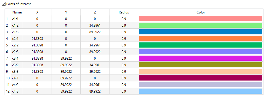
Points of Interest

For a calibration device, the points of interest are the beads embedded in the physical object. For each bead, you need to specify its 3D location and its radius. Specifying a colour is optional, but can be helpful when digitizing the bead locations in the X-ray images.
Note: The X-ray lab reference frame is implicitly defined by the 3D coordinates of the calibration device's points of interest.
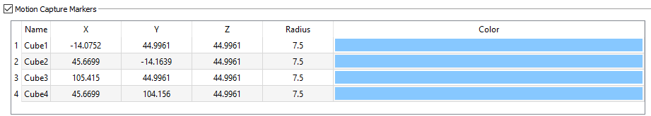
Motion Capture Markers
If you want to synchronize your dynamic X-ray images with motion capture data, you need to put at least three motion capture markers on the calibration device and specify their locations and radii in this section. The coordinates of these mocap markers are specified in the X-ray lab reference frame. Once they are tracked by the motion capture system during collection of the X-ray images of the calibration device, the transform from the X-ray lab frame to the motion capture frame can be computed (by CalibrateDSX).

Sample Calibration Device
- Name: cube
- Points of Interest:
- Motion Capture Markers:
Grid Devices
Add Grid Device
Click the arrow button to the left of the name of the session (in the example below it is named Day1) in the left hand field to expand the list. Left click on the Grid Devices label so that the Add Grid Device option appears. Click on Add Grid Device. Grid Devices are used to apply distortion correction to the X-ray images.

This will cause an arrow to appear to the left of the Grid Devices label. Click on the arrow in order to expand the list. It will expand to show the label newgrid.

Complete Grid Device
Click on the new grid device in the tree view to display its properties in the panel on the right.
General

- Name - The name entered will replace the newgrid tag in the tree on the left hand side of the screen.
- Type - the type of grid.
- Holes refers to a radiopaque sheet with punched or drilled holes.
- Beads refers to a radiolucent sheet with embedded radiopaque beads.
- X Spacing - the distance, in millimeters, between adjacent beads/holes in the grid object, along the X axis. The default value is 10.0.
- Y Spacing - the distance, in millimeters, between adjacent beads/holes in the grid object, along the Y axis. The default value is 10.0.
- XY Angle - the angle between the X and Y axes of beads/holes in the grid object. For hex grids, this parameter can be set to 60.0 or 120.0. The default value is 90.0.
- X Angle - the angle between the X axis of grid beads/holes and the X axis of the grid image. If the grid X axis is supposed to be aligned with the image intensifiers, set this parameter to 0.0. If the alignment of the grid X axis is unknown (common with hex grids of holes), set this parameter to a value outside the range -360.0 to 360.0, which tells CalibrateDSX to calculate the alignment. The default value is 999.9.
Sample Objects
For the sample data in this tutorial fill in the grid properties as specified below:

Trackable Objects
Add Trackable Objects
Click the arrow button to the left of the name of the session (in the example below it is named Day1) in the left hand field to expand the list. Left click on the Trackable Objects label so that the Add Trackable Object option appears. Click on Add Trackable Object. These objects represent bones or implants that will be tracked in the X-ray trials.

This will cause an arrow to appear to the left of the Trackable Objects label. Click on the arrow in order to expand the list. It will expand to show the label newobject.

Complete Trackable Objects
Click on the new object in the tree view to display its properties in the panel on the right.
General

- Name - The name entered will replace the newobject tag in the tree on the left hand side of the screen.
- Mocap Segment Name - The mocap segment name is entered if motion capture data will be used to position this object before tracking. The mocap segment name should be the segment name in the Visual3D kinematic model to which this object is rigidly attached.
- Weighted Center - Do not enter the Weighted Center coordinates. These will be calculated when you load the object into X4D, and are only for internal use in that program.
File Data
The File Data section contains the four data files for the object and is displayed when the checkbox is selected.

- Image File - This file is the segmented and cropped CT/MRI file that represents the object. It is generated in Surface3D (or third-party applications like Mimics or ScanIP). If you use Surface3D to create this file, you do not need to enter any of the parameters such as image size and voxel size; Surface3D will calculate them and automatically add them to the file specification. If you use a third-party application to create this file you will need to enter this information manually.
- Surface File - This file is the polygonal mesh representing the surface of the object. This file is generated in Surface3D (or a third-party application). If you use Surface3D to create this file, it will automatically add the file path and units to the subject file so you do not need to manually enter them here. If you use a third-party application to create this file you will need to enter this information manually.
- ROI Surface File - This file is the Surface File after regions of interest have been defined on it, and it has been transformed into its local (anatomical) reference frame. It is generated by Orient3D so you do not need to specify it manually here. If you export tracked DSX trials to a CMZ file for analysis in Visual3D, the ROI Surface File for each tracked object will be added to the CMZ. Visual3D expects these object surfaces to be defined in meters, so that is the default unit for these files.
- Inner Surface File - This optional file is used only by the Image Data Generator widget in Orient3D to make 3D image data (Image Files) from surface models. This widget is primarily used for generating simulated CT data from surface models created from MRI. If the object has an Inner Surface File when the Image Data Generator is used, voxels between the outer surface and the inner surface will be given the specified cortical density, and voxels inside the inner surface will be given the specified cancellous density. This creates more realistic simulated CT data then using only the Surface File and a constant cortical thickness. The Inner Surface File must be in the same units and reference frame as the Surface File. It should be a closed polygonal surface without holes, and it should not connect to or intersect with the outer surface.
For more information on importing image and surface files from third-party applications, follow the tutorial How To: Import Third-Party Image and Surface Files
Reference Frame
The Reference Frame section is displayed when the checkbox is selected.

- Reference Frame - This is the transformation from the CT frame of the object (defined implicitly by the Image File) to the local (anatomical) frame of the object. This transformation is calculated by Orient3D and does not need to be entered manually unless you determine the local frame of the object using a third-party program. In that case you can type in the values into the number fields or load a 4×4 matrix from a comma-delimited text file. If the number fields are blank it means that no local reference frame has been defined.
Landmarks
The Landmarks section is displayed when the checkbox is selected.

Points of Interest
The Points of Interest section is displayed when the checkbox is selected.

- Points of Interest - These are created in Surface3D (or Mimics or ScanIP), but can also be entered manually. An object must be created for each object you want to track in the x-ray trials (e.g., bones, implants), as well as an object for your lab’s calibration object.
Sample Trackable Objects
For the sample data in this tutorial two objects need to be created.
- Object 1
- Name - left_femur
- Mocap Segment Name - LeftFemur
- Type - bone
- No other data needs to be entered for this object.
- Object 2
- Name - left_tibia
- Mocap Segment Name - LeftTibia
- Type - bone
- No other data needs to be entered for this object.
Configurations
Add Configurations
Click the arrow button to the left of the name of the session (in the example below it is named PreOp) in the left hand field to expand the list. Left click on the Configurations Label so that the Add Configuration option appears. Click on Add Configuration.

This will cause an arrow to appear to the left of the Configurations Label. Click on the arrow in order to expand the list. It will expand to show the label newconfig.

Complete Configurations
Click on the new configuration in the tree view to display its properties in the panel on the right.
- General

- Name - The name entered will replace the newconfiguration tag in the tree on the left hand side of the screen.
- Date - The date that the data was collected.
- Lab to Mocap Transformation
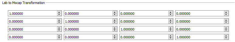
- Lab to Mocap Transformation - This provides the transformation between the lab space and the motion capture file. This information is calculated in CalibrateDSX, so it does not need to be manually entered.
- Setup
- A Setup section is automatically created in all configurations, which allows the two x-ray views to be defined and the parameters of the 3D configuration of the x-ray equipment to be entered.
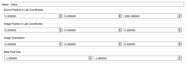
- Name - The name of the x-ray view. Rename view1 to inline and view2 to offset. Note: All of the view parameters below the name are calculated in CalibrateDSX, so they do not need to be entered here.
- Source Position in Lab Coordinates - This is the XYZ location of the x-ray source in the lab frame.
- Image Position in Lab Coordinates - This is the XYZ location of the geometric center of the x-ray image (not the perpendicular projection point of the x-ray source) in the lab frame.
- Image Orientation - These are the XYZ Euler angles expressing the orientation of the x-ray image in the lab frame.
- Base Pixel Size - This is the XY size of the pixels in the x-ray image, as calculated from the grid image.
- Calibration
- A Calibration section is automatically created for each Configuration, it includes three calibration trials.
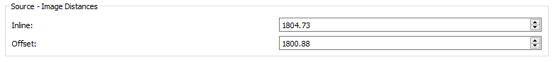
- Source: Image Distances - This panel is shown on the right hand side of the screen when Calibration is selected. The values entered are the approximate distances between the x-ray source and the x-ray image for each view. These values are used in the DLT algorithm that calculates the 3D configuration parameters. The values you specify here should be within a few millimeters of the actual distances (which the DLT will calculate).
- Uniformity
- The Uniformity trial is for the “blank” x-ray images, which are used to correct for non-uniformity in the x-ray intensity across the image.
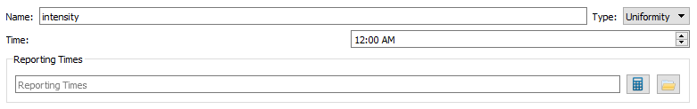
- Name - The name is initialized to 'intensity' and should not be changed.
- Type - The type drop down menu only contains the type 'Uniformity' since it is pre-set.
- Time - This is the time of the file being recorded.
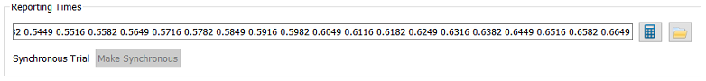
- Reporting Times - The Reporting Times for each trial will be calculated automatically from the views’ frame times when the trial is first loaded into an application (or when you press the calculate button), but they can also specified by typing the value into the field or browsing for a file.
- View
- For the Uniformity and Distortion trials, select the views for which you have x-ray data using the checkboxes, then click on the view name to show its properties in the panel on the right.
- Inline
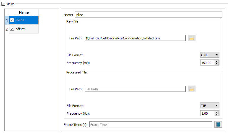
- Name - This is the name that will be listed in the name table on the left side of the View section.
- Raw File - The Raw File section contains the uncorrected x-ray image sequence captured by the camera. If your raw x-ray file has frame times specified in it (for example, CINE files) you do not need to specify the frequency or the frame times. DSX Manager will read this information from the file and store it in the Frame Times field when you first load the trial into an application, or when you press the calculate button.
The settings for Uniformity - Inline should be:
  - File Path to iwhite3.cine
  - File Format CINE, and
  - Frequency 150.00.
- Processed File - The Processed File is the corrected image sequence output by CalibrateDSX. If you do not use CalibrateDSX to correct your x-ray files, you can specify the processed x-ray files for the trial and leave the raw files blank.
- Frame Time(s)
- Offset
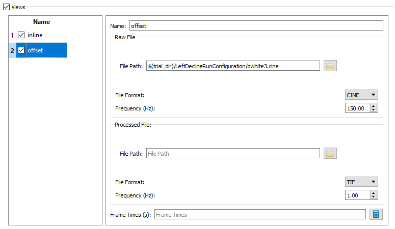
- Name - This is the name that will be listed in the name table on the left side of the View section.
- Raw File - The Raw File section contains the uncorrected x-ray image sequence captured by the camera. If your raw x-ray file has frame times specified in it (for example, CINE files) you do not need to specify the frequency or the frame times. DSX Manager will read this information from the file and store it in the Frame Times field when you first load the trial into an application, or when you press the calculate button.
The settings for Uniformity - Offset should be:
  - File Path to owhite3.cine
  - File Format CINE, and
  - Frequency 150.00.
- Processed File - The Processed File is the corrected image sequence output by CalibrateDSX. If you do not use CalibrateDSX to correct your x-ray files, you can specify the processed x-ray files for the trial and leave the raw files blank.
- Frame Time(s)
- Distortion
- The Distortion trial is for the images of the grid object, which can be either a radiopaque sheet with holes in it, or radiopaque beads on a radiolucent sheet. The regular spacing of the holes/beads is used to correct for distortion of the xray trajectories in the field of view.
- The setting for Distortion - Inline should be:
- File Path to igrid3.cine
- File Format CINE
- Frequency 150.00.
- The settings for Distortion - Offset should be:
- File Path to ogrid3.cine,
- File Format CINE, and
- Frequency 150.00
- 3D
- The 3D trial is for the images of the calibration object. These images are used to calculate the 3D configuration parameters of each view.

- Name - The name is initialized to 'calibration' and should not be changed.
- Type - The type drop down menu only contains the type '3D Calibration' since it is pre-set.
- Time - This is the time of the file being recorded.

- Reporting Times - The Reporting Times for each trial will be calculated automatically from the views’ frame times when the trial is first loaded into an application (or when you press the calculate button), but they can also specified by typing the value into the field or browsing for a file. For the 3D trial, the views are specified the same way as in the Uniformity and Distortion trials, but there are additional parameters related to motion capture data and the calibration object.
- Mocap Parameters
- The Mocap Parameters section contains the name of the C3D file with the motion capture data for the calibration object. This file is needed in order to calculate the transformation between the motion capture reference frame and the X-ray reference frame.

- The file path should lead to the cube3.c3d file in the configuration's file.
- Tracked Bodies
- The Tracked Bodies section is available when the checkbox is selected.
- In the Tracked Bodies section of the 3D trial, check the box for the calibration object defined in the session’s Objects section. For this tutorial, check the cube option. You do not need to specify any of the calibration object’s files; they will be created during the calibration process.
- Views
- The Views section is available when the checkbox is selected.
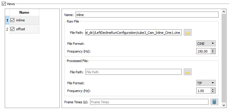
- The setting for 3D - Inline should be:
- File Path to cube3_Cam_Inline_Cine1.cine,
- File Format CINE, and
- Frequency 150.00.


This will cause an arrow to appear to the left of the Trials Label. Click on the arrow in order to expand the list. It will expand to show the label newtrial.

Complete Trials
The Trials section in a configuration contains all of the motion and reference trials captured in that configuration. Reference trials are usually static trials in which the subject is stationary, but they do not have to be static. If you want to use motion capture data to initialize the bone poses for a motion trial, that motion trial must be associated with a reference trial (this association is explained in detail in the motion capture guide).
- General

- Name - This is the name that will appear in the tree on the left hand side of the screen.
- Type - The options in the drop down menu are Reference and Motion, indicating the type of the trial. For LDR 2, choose Motion.
- Reference Trial - The drop down menu of Reference Trials has a list of all the Reference Trials that have been created for the subject. If the only option is “none,” then no Reference Trials have been created in the subject. Once the Reference Trial has been completed as described below, this section can be completed and should be set to LeftStand.
- Time - This is the time that the trial was collected. For this tutorial use 3:54 PM.
- Mocap Parameters
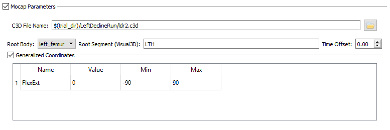
- C3D File Name - The C3D file that should be loaded for this tutorial is ldr2.c3d.
- Time Offset - The Time Offset is the offset, in seconds, between the start time of the motion capture system and the start time of the X-ray system for the trial. That is, the data in the C3D file starts Time Offset seconds before the data in the X-ray files. For this tutorial the Time Offset can be left at 0.00.
- Tracked Bodies
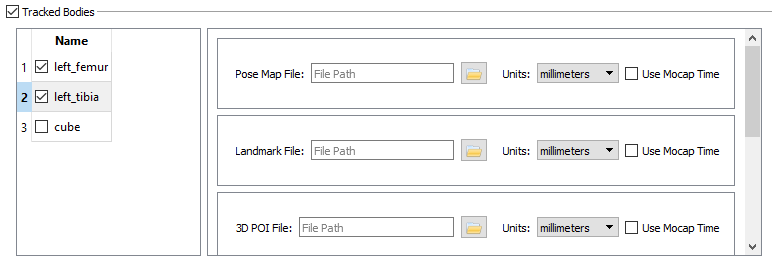
- Note: For Motion Trials the bodies' files do not need to be specified prior to processing the data. As you track the bodies and their points of interest in the other DSX programs, these files will be created and added to the subject file.
- Views
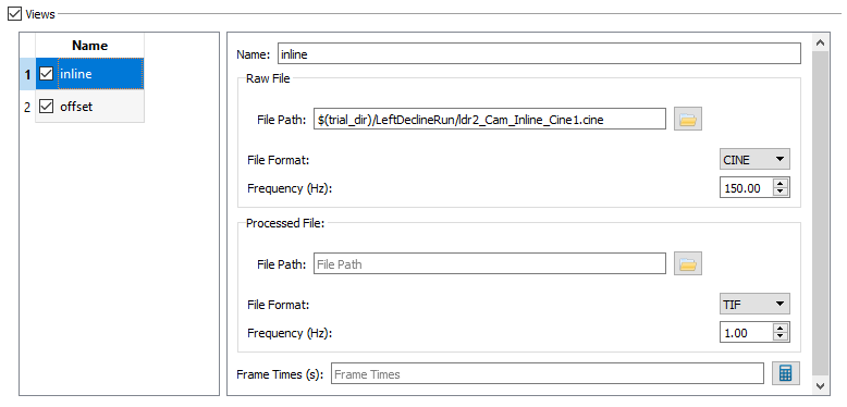
- The settings for Trials - Inline should be:
- File Path to ldr2_Cam_Inline_Cine.cine,
- File Format CINE, and Frequency 150.00.
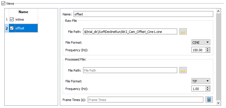
- The settings for Trials - Offset should be
- File Path to ldr2_Cam_Offset_Cine1.cine,
- File Format CINE, and Frequency 150.00.


Second Configuration
Add A Second Configuration
Using the instructions above, create a second configuration named “Left Level Walk” and complete it with the following information:
- General
- Name - Left Level Walk
- Setup
- Name view1 - inline
- Name view2 - offset
- Calibration - General
- Inline - 1796.0
- Offset - 1795.0
- Calibration - Uniformity
- Name - intensity
- Type - Uniformity
- Time - 3:54 PM
- View Name - inline
- Raw File
- File Path - iwhite4.cine
- File Format - CINE
- Frequency (Hz) - 150.0
- View Name - offset
- Raw File
- File Path - owhite4.cine
- File Format - CINE
- Frequency (Hz) - 150.00
- Calibration - Distortion
- Name - grid
- Type - Distortion
- Time - 3:54
- View Name - inline
- Raw File
- File Path - igrid4.cine
- File Format - CINE
- Frequency (Hz) - 150.00
- View Name - offset
- Raw File
- File Path - ogrid4.cine
- File Format - CINE
- Frequency (Hz) - 150.0
- Calibration - 3D
- Name - cube
- Type - 3D Calibration
- Time - 3:54 PM
- Mocap Parameters
- C3D File Name - cube4.c3
- Tracked Bodies - Checkmark next to cube
- View Name - inline
- Raw File
- File Path - cube4_Cam_Inline_Cine1.cine
- File Format - CINE
- Frequency (Hz) - 150.00
- View Name - offset
- Raw File
- File Path - cube4_Cam_Offset_Cine1.cine
- File Format - CINE
- Frequency (Hz) - 150.00
- Trials - LLW 2
- Name - LLW 2
- Type - Motion
- Reference Trial - LeftStand
- Time - 3:54 PM
- Mocap Parameters
- C3D File Name - llw2.c3d
- Time Offset - 0.00
- Generalized Coordinates
- Name - FlexExt
- Min - -90
- Max - 90
- Tracked Bodies - Checkmark next to left_femur and left_tibia
- View Name - inline
- Raw File
- File Path - llw2_Cam_Inline_Cine1.cine
- File Format - CINE
- Frequency (Hz) - 150.00
- View Name - offset
- Raw File
- File Path - llw2_Cam_Offset_Cine1.cine
- File Format - CINE
- Frequency (Hz) - 150.00
Reference Trials
The Left Level Walk Configuration includes a second Trial which is a Reference Trial. Reference trials contain three additional mocap parameters. Once a Reference Trial is created then it can be specified in the general section of the other trials, as described above.
- General

- Name - LeftStand
- Type - Reference
- Time - 3:55 PM
- Mocap Parameters
- If the Mocap Parameters section does not update the fields automatically, navigate to another screen and back to the reference trial.
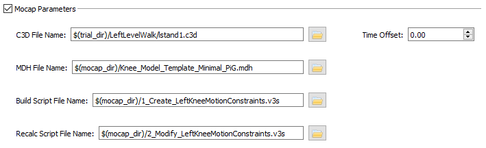
- C3D File Name - For this tutorial, use lstand1.c3d.
- Time Offset - 0.00
- MDH File Name - This is the name of the file containing the definition of the Visual3D kinematic model. For this tutorial, use Knee_Model_Template_Minimal_PiG.mdh.
- Build Script File Name - This is the file with the commands that creates the kinematic constraints of the model. For this tutorial, use 1_Create_LeftKneeMotionConstraints.v3s.
- Recalc Script File Name - This is the file of commands that re-apply the kinematic constraints so you can interact with the model in X4D. For this tutorial, use 2_Modify_LeftKneeMotionConstraints.v3s.
- Generalized Coordinates - The Generalized Coordinates are the degrees of freedom in the kinematic model. For example, when tracking the knee joint, the tracked bodies will likely be the distal femur, proximal tibia, and patella, with the motion of all three bones specified as functions of a single generalized coordinate– the knee flexion angle. To add a Generalized Coordinate, left-click on the empty table and select Add Generalized Coordinates. For this tutorial the name should be FlexExt, the Min should be -90, and the Max should be 90.
- The files listed above are explained in detail in the motion capture guide.
- Generalized Coordinates
- Name - FlexExt
- Min - -90
- Max - 90
- Tracked Bodies
- Place a checkmark next to left_femur and left_tibia.
- Views
- Name - inline
- Raw File
- File Path - lstand1_Cam_Inline_Cine1.cine
- File Format - CINE
- Frequency (Hz) - 150.00
- Name - offset
- Raw File
- File Path - lstand1_Cam_Offset_Cine1.cine
- File Format - CINE
- Frequency (Hz) - 150.00

