Table of Contents
Surface3D Overview
Surface3D segments objects (bones, implants, etc.) from CT data for use in model-based tracking, and it creates surface models of these objects for subsequent kinematic analysis of the tracking results. After segmenting an object from the CT data, the CT data can be cropped and masked, and then saved to a RAW or TIFF file. These cropped image files with just one object in them, are used by X4D to generate DRRs for model-based tracking. It can also generate a polygonal surface model from the currently segmented object using a marching cubes algorithm, and save it to an OBJ file. The surface models are used by Orient3D to define anatomical references and regions of interest (for distance map calculations), and by Visual3D for kinematic analysis. Surface3D also allows you to identify landmarks (e.g., ligament attachments) and points of interest (e.g., implanted beads) in the image data.
Tutorials
Work through these tutorials to learn how to use Surface3D:
And learn about the Image and Surface Files used in DSX.
Menus
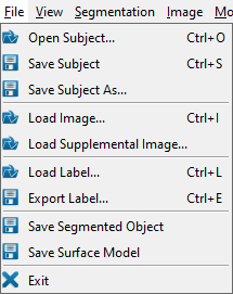
File Menu
- Load Subject… (Ctrl + O) loads a subject file.
- Save Subject (Ctrl + S) saves the currently loaded subject to its existing subject file.
- Save Subject As… saves the currently loaded subject to a new subject file.
- Load Image… (Ctrl + I) loads 3D image data for segmentation. This command is meant to be used when you do not have a subject file, but just want to load image data and segment it. Currently, Surface3D supports DICOM, RAW, and TIFF formats. At least one of the image files needs to have the appropriate extension so that it can be selected in the file dialog. If a subject is currently loaded, it is closed.
- Load Supplemental Image… loads 3D image data for an object that already has a segmented image file. This command is meant to be used for handling multiple DICOM stacks related to processing a single object. For example, when modeling the femur for a knee study, you might have one image stack for the distal femur and a second one with a few slices of the femoral head for locating the hip center. In this case you would load the distal femur stack for segmentation and surface model creation, then load the hip stack as a supplemental image for defining the hip center landmark.
- Load Label… (Ctrl + L) loads an earlier saved segmentation from file. Surface3D supports the TIFF and RAW formats. Loading a segmentation from file will erase the current label and label edits. The menu item becomes enabled after image data has been loaded. The size of the segmented image data in the selected file must be the same as the size of the currently loaded image data.
- Export Label… (Ctrl + E) saves the current segmentation to file. Surface3D supports the TIFF and RAW formats.
- Save Segmented Object saves the currently loaded image data to a RAW or TIFF file. It is meant to be called after the data has been masked and cropped to a label. If a subject is loaded and the object in the subject already has a link to a segmented image file, this file will be overwritten without notification. If a link does not already exist, you will be prompted to select a new file name. You can then also choose the desired format (OBJ or IV) and units.
- Save Surface Model saves the polygonal surface model to an OBJ or IV file. If a subject is loaded and the object in the subject already has a link to a surface model file, this file will be overwritten without notification. If a link does not already exist, you will be prompted to select a new file name.
- Exit exits the program. The program can also be closed using the X in the top right corner of the program window.
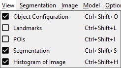
View Menu
- Object Configuration (Ctrl + Shift + O) toggles the appearance of the dockable Object Configuration widget.
- Landmarks (Ctrl + Shift + L) toggles the dockable Landmarks widget, which has a list of the landmarks in the selected object. This item appears in the menu only when a subject file is loaded and an object is selected.
- POIs (Ctrl + Shift + P) toggles the dockable POIs widget, which has a list of the points of interest in the selected object. This item appears in the menu only when a subject file is loaded and an object is selected.
- Segmentation (Ctrl + Shift + S) toggles the dockable Segmentation widget, which contains the editable list of object labels that can be used for segmentation.
- Histogram of Image (Ctrl + Shift + H) toggles the dockable widget with the histogram of the image data.
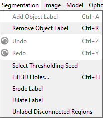
Segmentation Menu
- Add Object Label (Ctrl + A) adds a segmentation label to the Segmentation widget. Surface3D currently only supports one segmentation label.
- Remove Object Label (Ctrl + R) deletes the currently selected segmentation label.
- Undo (Ctrl + Z) undoes the last manual edit to the segmentation label.
- Redo (Ctrl + Y) redoes the last undone manual edit to the segmentation label.
- Select Thresholding Seed allows the user to pick a point(pixel) in any of the 2d render windows, which will then be used as a seed for 3d thresholding using the threshold values set in the Histogram widget.
- Fill 3D Holes… (Ctrl + H) first opens a dialog with some descriptive text and the opportunity to change the value of the 3D Hole Threshold parameter (default: 2000). When the user decides to go ahead, the command automatically fills all 3D holes in the current segmentation. The algorithm finds each unlabelled voxel next to a labelled voxel and uses a flood-fill algorithm to find all unlabelled voxels that are connected to it. If the size of this region is less than the value of the 3D Hole Threshold parameter, then the region is labelled with the current label.
- Erode Label automatically erodes the segmentation. The basic effect is to erode away the boundaries of regions of the currently selected label. Thus areas of label pixels shrink in size, and holes within those areas become larger.
- Dilate Label automatically dilates the segmentation. The basic effect is to gradually enlarge the boundaries of regions of the currently selected label. Thus areas of label pixels grow in size, and holes within those areas become smaller.
- Unlabel Disconnected Regions unlabels all voxels that are not connected to the selected voxel. It is useful for unlabelling large sections of the image data after you have labelled the bone of interest. For example, when segmenting a vertebra from spine images, the appropriate threshold settings often label all of the vertebrae because of their close proximity. Rather than manually erase the label from all of these unwanted voxels, you can use this command. Start by completely labelling the bone of interest. Then erase the label from all unwanted voxels bordering this bone, so that the bone is not connected to any other labelled regions. Then choose this command and select any voxel in the bone of interest.
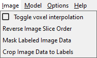
Image Menu
- Toggle Voxel Interpolation toggles the method used to render the image data voxels and the segmentation label voxels. When this option is unchecked, each voxel is rendered with a constant color (flat shading). When this option is checked a smooth shading technique is used, in which a voxel's color is smoothly interpolated between its neighbors.
- Reverse Image Slice Order reverses the slices of the loaded image, i.e., the first slice becomes the last one, and the last slice the first one. The segmentation and its edits are automatically adjusted, as are the locations of the POIs and landmarks.
- Mask Labeled Image Data sets all unlabeled voxels in the current image to zero. This action cannot be undone.
- Crop Image Data to Labels reduces the size of the image to the bounding box of the current segmentation label (i.e., the minimum dimensions that include all labeled voxels). This action cannot be undone.
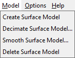
Model Menu
- Create Surface Model creates a polygonal surface model from the current segmentation label. It uses a marching cubes algorithm to find an isosurface from the set of labelled voxels. For best results, the labelled voxels should not have any holes in the interior.
- Decimate Surface Model… reduces the number of vertices and polygons in the surface model. Decimation is controlled by the Decimation Factor parameter, which specifies the approximate percentage of polygons that will be removed from the surface. For example, if the parameter is set to 0.2, approximately 20% of the polygons will be removed each time the decimate command is performed. Decimating too much may remove small details of the surface model that are needed for tracking. This action cannot be undone.
- Smooth Surface Model… smooths the surface model by making small adjustments to the vertex positions using a windowed sinc function. This algorithm is controlled by the following three parameters. Pass-Band Frequency specifies the low-pass cutoff frequency (normalized to the range 0.0 to 2.0). Lower values produce more smoothing. Smoothing Iterations is the number of iterations performed each time the smoothing command is executed. Preserve Feature Edges controls the smoothing of sharp interior edges on the surface model. When this option is selected, edges with angles greater than Feature Angle will not be smoothed. Smoothing may shrink the surface model towards its center, and this action cannot be undone.
- Delete Surface Model deletes the current surface model.
Options Menu
Help Menu
- Help (F1) opens the Surface3D wiki page in the default browser.
- About… displays a dialog with information about Surface3D, including the installed version number. It also contains the Deactivate button, for deactivating your DSX suite license.
Widgets
The Surface3D application contains six widgets:


