Table of Contents
Calculations
Graphics
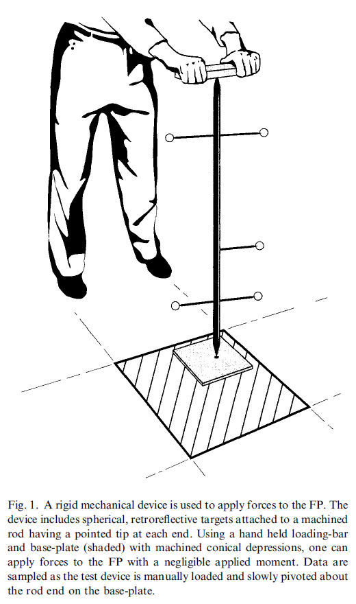
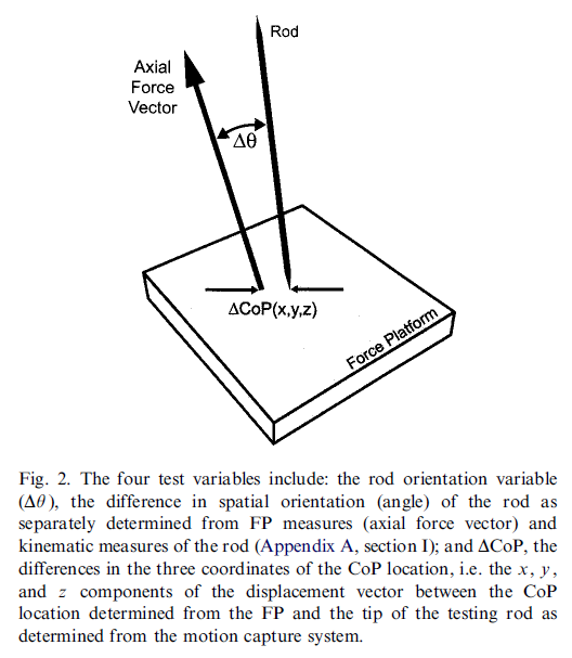
The following graphics are from the CalTester Paper Holden JP, Selbie WS, Stanhope SJ, “A proposed test to support the clinical movement analysis laboratory”.
Calculations
The following calculations and explanations are from the CalTester Paper Holden JP, Selbie WS, Stanhope SJ, “A proposed test to support the clinical movement analysis laboratory”.
Section I : Calculating the rod orientation variable under the assumed condition of static equilibrium
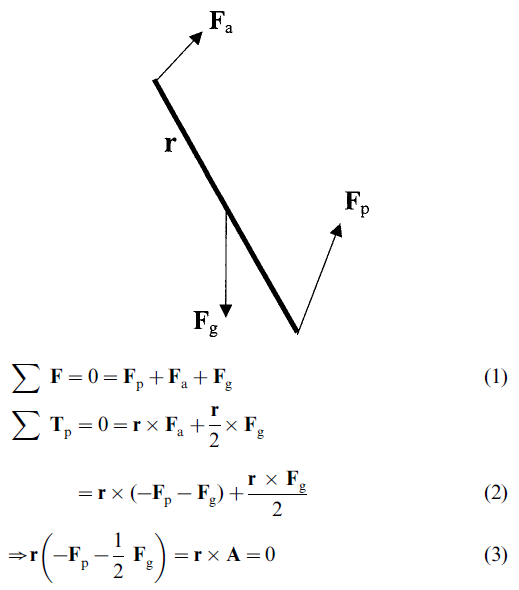
Free-body diagram of testing device: Fp, ground reaction force; Fg, gravitational force (weight); Fa, applied force; r, position vector between tips (p to a) of testing device rod:

Thus, r and A are parallel and the test device rod orientation ® is defined entirely by the vector quantity A that is derived from FP measurements (Fp) and the physical characteristics of the testing device (Fg/2, i.e.the weight of the rod and its center of mass location; in this case, half the rod length).

The rod orientation variable (  ) is determined from the dot product of the unit vector along A and the unit vector aligned with the long axis of the rod ® as determined using the motion capture components.
Section II : Equation for evaluating the static equilibrium assumption
Under 2D dynamic conditions, the following holds:

Rewriting the left-hand side of Eq. (4)

Rearranging Eq. (5), the magnitude of the angular displacement (  ) between vectors r and A due exclusively to the inertial terms can be isolated:

where r is the length of the testing device rod, Icg the moment of inertia of the test device rod about the center of mass location, m the mass of the testing device rod and  is the angular acceleration of the testing device rod relative to an inertial reference frame.
CalTesterPlus does not calculate  since it operates under the assumption that there is no angular acceleration. For this reason it is important to move the CalTester rod slowly at a constant speed.


