Table of Contents
Parameters
This section describes in details the parameters used by the various processing functions.
Comment
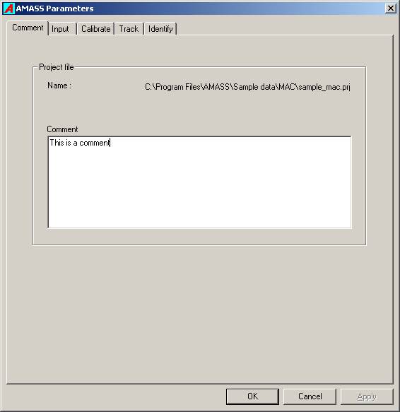
This tab displays the folder and name of the current project file, and allows the user to enter a comment describing the project.
The calibration tab contains all parameters required by the calibration, and the tracking tab only has those parameters required for tracking. There is no interaction between the two sets.
Input
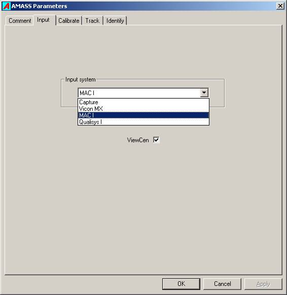
The Input tab contains a list box that allows the user to choose from a list of supported camera systems. The selection of Capture will enable the Capture… button in AMASS shell provided that the cen file radio button is also selected, and will permit the user to launch the C-Motion capture program.
The selection of any other system will enable the leftmost radio button in the AMASS shell and supply a raw camera data file extension. The user can then browse for folders containing raw camera data files and translate them to .cen files using the Convert function.
Placing a check in the check box instructs the software to call the ViewCen program automatically after each .cen file is completed.
Calibrate
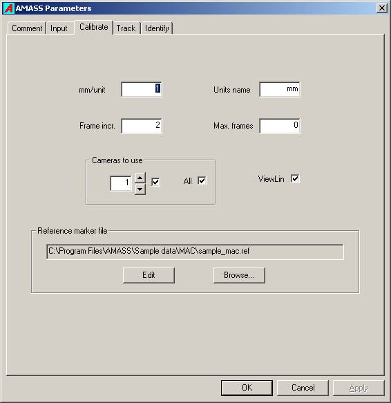
The Calibrate page displays all user modifiable parameters for the calibration. On inspection it will be seen that not one of the parameters refers to the calibration computation itself, relieving the user from making difficult and confusing decisions with respect to the complex calculations that are involved in the calibration process.
mm /unit
In AMASS all distance measures are expressed in terms of a single unit of length whose size is specified through this parameter. The user should enter their size of the desired length units in millimeters. For example, if it is desired to have all output in centimeters then the required value is 10.0. The default unit length is millimeters, with a value of 1.0.
Units name
This entry allows the user to enter the name of the length units being used. It accepts a name length of up to 20 characters, and the default name is millimeters (mm).
Frame Increment
In situations where a large number of frames are collected for a calibration, or in captures involving high frame rates, using every frame in the calibration calculation may be inappropriate. In that case the user can choose to use fewer frames from the .cen file, e.g. every second or every third frame. For example, entering a value of 5 will result in every 5th frame being used for the computation.
Maximum frames
This entry specifies the maximum frame number to be used for the calibration. An entry of zero implies all frames recorded in the .cen file. Note that the number of frames actually used will be influenced by the Frame Increment entry.
Cameras to use
Occasionally it may be useful to exclude one or more cameras from the calibration because a camera is malfunctioning, a poorly calibrating camera is influencing the calibration of the other cameras, or you may wish to investigate the contribution of a particular camera on the calibration. The check boxes in this group can be used to ignore data from any camera during the calibration.
ViewLin
Check this box if you want ViewLin to run automatically after every calibration.
Reference marker file
This entry holds the full name of the file that contains the x, y, and z coordinates of the static Reference markers that will be used to translate the calibration data to the desired Global Coordinate System. You may browse for an existing .ref file or create a new one.
To create a new Reference marker file select Browse…, and in the browse window type in a file name, select a destination folder, and then click Open. A window will pop up asking if you wish to create a new file. If you answer Yes a NotePad window will open allowing you to enter the coordinates of your reference markers. After the comment line type in the x, y, z coordinates of each marker, one marker per line, and then save the file.
The location of each marker is specified in the “desired” laboratory coordinate system.
Each row of the ref file contains the x y x components of the marker.
There is no specified order to the rows, which means that you can list the markers in any order that you want. AMASS creates a laboratory coordinate system, such that the markers are located at the specified x y z values.
If, for example, the centroids of all markers are at a height of 20 mm, the z-component of each row should have the value 20.
No Reference Marker File
The system will calibrate without any reference marker file, i.e. .ref file and provide a default global system defined by the first three camera locations. Any time there is a ref file with recognized maker distribution, the calibration and subsequent data are output in the ref file coordinate system.
To clear the file name select Browse… followed by Cancel in the browse window.
Example .ref file
An example reference file for an L-Frame that has four markers.
Comment line 30.0 20.0 49.5 130.0 20.0 49.5 260.0 20.0 49.5 20.0 260.0 49.5
Track
Predictor error
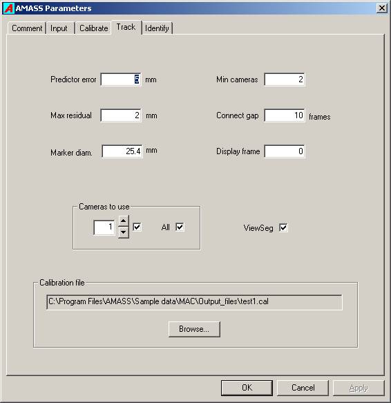
During tracking 3D marker positions are gathered into trajectories or segments, and typically five previous frames of a marker’s locations are used to predict the marker’s position in the next frame. The Predictor error parameter defines how far the marker’s calculated location in the next frame may be from its predicted location in order for the marker to be considered to belong to the current segment. If there are no markers found within the Predictor error distance of the predicted location, the segment is terminated. Setting this value too low will result in many short segments, while setting it too high may cause segment crossovers (the trajectory of two markers are swapped). The default value is 5mm.
The predictor error should ideally be set with regard to a) units being used, b) marker size, c) minimum expected marker separations, and d) residual values given by the calibration. Although it is true that in many situations it is not very sensitive. Of course, the units are critical.
Maximum residual
For any ray from a marker to a camera, the residual for that ray is defined as the shortest distance from the calculated location of the marker to the ray. Two or more rays from a marker to different cameras are needed to calculate or “reconstruct” the most likely location of the marker in space. The Maximum residual parameter defines the largest value the residual may have for a ray. If a ray has a residual larger than this maximum, the observation for the camera recording that ray is excluded from that marker’s position computation. If this number is set too low many rays will be erroneously excluded from the marker position computations resulting in segment breakups and less accurate marker locations. If it is set too high then rays will be associated with markers they do not belong to, resulting in phantom markers, inaccurate marker locations, and segment crossovers. The default value is 2mm.
Marker diameter
This parameter conveys the size of the markers being used. However the program is not very sensitive to its value. One use is to ensure that no two reconstructed markers are closer together than this distance. Again, the distance must be expressed in the chosen user units. The default value is 25.4mm which is the marker diameter in the standard sized wand.
The marker diameter parameter only refers to the tracking of trials, not the calibration (which is fixed in the wand), and should be set to his marker diameter.Tracking can be affected by the marker diameter parameter.
Minimum cameras
A marker must be recorded in the images of at least two cameras for its position is to be reconstructed. If three or more cameras observe a marker the calculated marker location is likely to be more accurate and the system is less prone to creating phantom markers resulting from the accidental intersection of rays belonging to different markers. Hence with systems that routinely record markers with more than two cameras it may be useful to require that only markers imaged by more than two cameras be utilized. The default value is 2 cameras, but a value of 3 can dramatically decrease the number of “phantom” or junk markers produced.
Connect gap
After all segments have been generated the program can sort through the data and attempt to combine different segments into a single segment. This valuable tool typically greatly reduces the number of segments the user has to identify. It does so by comparing the direction and location of the end of one segment to the directions and locations of the beginnings of all other segments. If it finds a close match, and the end of the first segment is no more than Connect gap frames from the start of the second segment, both segments are combined into a single segment. This single segment will not be continuous but will display a gap in the ViewSeg graph. This parameter should be used with caution and its optimal value will depend upon the application. Setting it too high may result in segments being combined incorrectly. Its optimal value will depend upon the application, but a common value is 10 frames. A value of zero indicates that no connections should be carried out.
Display frame
The tracking program can be paused at any frame and allows the user to examine the marker reconstruction geometry. This facility is useful in diagnosing tracking problems and also serves as a very useful teaching tool. The graphics screen displays all rays, calculated marker locations, ray residuals, and predicted marker positions, and allows image manipulation by using use of the mouse. CURRENTLY THIS CAPABILITY IS INCOMPLETE.
Cameras to use
Occasionally it may be useful to exclude one or more cameras from the tracking because a camera is malfunctioning, or you may wish to investigate the contribution of a particular camera on the tracking. The check boxes in this group can be used to ignore data from any camera during the tracking.
ViewSeg
Checking this box causes the ViewSeg to be run automatically after each trial is tracked.
Calibration file
The Calibration file box specifies the folder and name of the calibration file that is to be used for the tracking computations. You may Browse… for it in the Track window of the parameters, or achieve the same result by clicking on the Apply button in the ViewLin widow for the calibration.
Identify
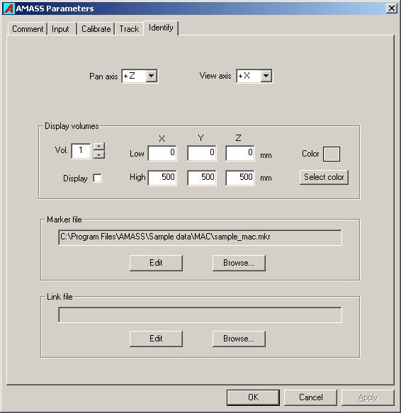
The Identify parameters provide input to the Identify program which allows the user to associate maker labels with the segments generated by the Track program.
Pan axis
When the left mouse button is held down and the mouse is dragged left or right in the Identify 3D view display, the Pan axis defines the direction of the axis about which the view will be rotated. The user may select the negative or positive direction of any of the three Global Coordinate System (GCS) axes.
View axis
This setting determines along which GCS axis the initial view of the markers is presented. During identification the view will typically be changed by the user as the image is manipulated by panning, tilting, and zooming.
Display volumes
The user may create up to ten “virtual” boxes in the Identify 3D view to mark regions of interest and aid in identification of segments. The boxes are defined by Low and High corner points in the GCS, where every Low coordinate is less than any corresponding High coordinate. Any box may be reduced to a plane by the entry of the same value in a common Low and High coordinate, i.e. if the floor is at the z-coordinate of -20, then entering -20 in the z-component of Low and High corners will cause a plane to be drawn at z = -20 user units. The size of the plane is specified by the other two coordinates.
Volume number
This box allows the user to select the volume number to be edited.
Display
The check box tells whether the particular box is to be displayed when the Identify program starts. Within Identify the facility exits to turn on and off the display of individual volumes.
Low coordinates
These three values hold the X, Y, and Z coordinates of the Low corner of the box.
High coordinates
These three values hold the X, Y, and Z coordinates of the High corner of the box. Each High coordinate value must be larger than the corresponding Low corner value. Only one (x, y, or z) coordinate of Low and High corners may be equal, in which case a plane will be drawn.
Color
The user can choose a color for the wire frame of each box when it is displayed. The Select color button presents a color picker window from which the user can select a standard color or create a custom color.
Marker file
The marker (.mkr) file is a file containing the marker labels that the user applies to the segments during the identification process. Clicking the Edit button launches Notepad and allows the user to edit the file. Clicking on the Browse… button allows the user to load an existing .mkr file or create a new one.
To create a new Marker label file, click Browse…, and in the browse window type in a file name, select a destination folder, and then click Open. A window will pop up asking if you wish to create a new file. If you answer Yes a NotePad window will open allowing you to enter marker labels. After the comment line type in one marker label per line, and then save the file. A marker description (32 characters maximum) may also be added to each marker label after a slash (/).
Note that if the .seg file you are processing has saved identifications, the marker file must have at least as many labels as the highest numbered identified marker.
Example .mkr file
An example .mkr contains a comment line and a marker name on each line:
This first line is a comment line. one two three four
Link file
This entry accepts the name of a Link (.lik) file which contains a list of marker label pairs that are to be joined in the 3D view. Clicking the Edit button launches Notepad and allows the user to edit the file. Clicking on the Browse… button allows the user to load an existing .lik file or create a new one.
To create a new Link file, click Browse…, and in the browse window type in a file name, select a destination folder, and then click Open. A window will pop up asking if you wish to create a new file. If you answer Yes a NotePad window will open allowing you to enter links. After the comment line type in one link per line, and then save the file.
Reference markers
Reference markers are static markers whose 3D coordinates in the Global Coordinate System (GCS) are stored in a Reference marker (.ref) file. These data enable the transformation of all output 3D locations to the GCS.
If reference markers are not present, their data are not provided, or the markers cannot be identified during the calibration, the resulting GCS is defined by the first three cameras that calibrate for the total system. The first camera is placed at the origin, the second camera is placed on the positive x-axis, and the third camera is placed in the x-y plane with the y-coordinate being positive. If only two cameras calibrate then the orientation of the x-y plane will be arbitrary.
The calibration program is capable of accommodating and identifying any number of reference markers provided that reasonably accurate marker locations are supplied. A minimum of three markers is required to define the GCS. There are no restrictions on where the static markers can be placed with the provision that they must be recorded in the calibrated image areas of at least two cameras, and the markers do not form a symmetrical distribution. The reference markers are automatically identified and their distribution is fitted by a least-squares technique to define the transformation to the GCS.
The format of the .ref file is simple ASCII with the first line being devoted to a comment, followed by any number of lines, each containing the x, y and z coordinates of a reference marker. The x, y, and z coordinates may be separated by spaces, commas, or tabs. Clicking the Edit button launches Notepad and allows the user to edit the file. Clicking on the Browse… button allows the user to load an existing .ref file or to create a new one.
To create a new Reference file click Browse…, and in the browse window type in a file name, select a destination folder, and then click Open. A window will pop up asking if you wish to create a new file. If you answer Yes a NotePad window will open allowing you to enter marker labels. After the comment line type in one set of marker coordinates per line, and then save the file.
Marker labels
The format of the .mrk file is simple ASCII with the first line being devoted to a comment, followed by any number of lines, each containing a marker label, and optionally a marker description after a slash “/” character.
Links
The format of the .lik file is simple ASCII with the first line being devoted to a comment, followed by any number of lines, each containing two marker labels separated by a hyphen. The Link (.lik) file defines pairs of markers labels (which must exist in the .mrk file) that designate which markers are to be connected in the Identify screen.

