Table of Contents
Tracking
The Track program accepts a .cen file, the tracking parameters, and a .cal file, and runs without any user intervention to produce a .seg file containing three-dimensional reconstructed marker segments. A segment is a part of a marker trajectory extending over multiple frames. The marker positions are expressed in the user distance units in the Global Coordinate System as defined by the Reference markers during the system calibration.
During tracking the program uses the system calibration data to transform all ray directions from every marker, for every camera, to the Global Coordinate System. Then it searches through all rays to find ones which pass in close proximity to each other in order to identify rays belonging to the same markers. The clusters of ray intersections are then reduced to single points representing the most likely location of the markers, and their positions are tracked across frames to yield segments. If a marker is not observed by at least two cameras its segment will terminate, to be commenced again as a new segment when it is again observed by at least two cameras.
The ability to reliably identify rays observed by different cameras that belong to the same marker is strongly dependent upon the accuracy of the calibration. Rays that do not tightly intersect cannot reliably be assigned to a single marker, resulting in poor tracking, “phantom” markers (caused by the program combining rays that actually come from different markers), and gaps in the marker segments. Hence, even if your experimental requirements do not call for high accuracy, the quality of the calibration is critical to effective marker trajectory generation.
Note that all distance units are user units as were specified in the calibration parameters.
Parameters
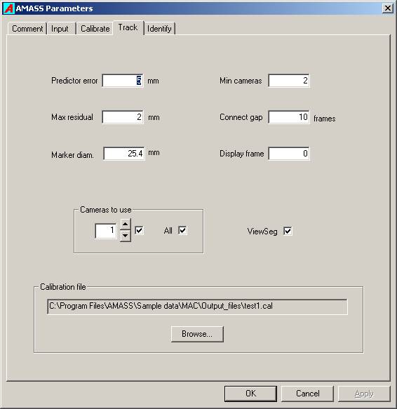
Predictor error
During tracking 3D marker positions are gathered into trajectories or segments, and typically five previous frames of a marker’s locations are used to predict the marker’s position in the next frame. The Predictor error parameter defines how far the marker’s calculated location in the next frame may be from its predicted location in order for the marker to be considered to belong to the current segment. If there are no markers found within the Predictor error distance of the predicted location, the segment is terminated. Setting this value too low will result in many short segments, while setting it too high may cause segment crossovers (the trajectory of two markers are swapped). The default value is 5mm.
The predictor error should ideally be set with regard to a) units being used, b) marker size, c) minimum expected marker separations, and d) residual values given by the calibration. Although it is true that in many situations it is not very sensitive. Of course, the units are critical.
Maximum residual
For any ray from a marker to a camera, the residual for that ray is defined as the shortest distance from the calculated location of the marker to the ray. Two or more rays from a marker to different cameras are needed to calculate or “reconstruct” the most likely location of the marker in space. The Maximum residual parameter defines the largest value the residual may have for a ray. If a ray has a residual larger than this maximum, the observation for the camera recording that ray is excluded from that marker’s position computation. If this number is set too low many rays will be erroneously excluded from the marker position computations resulting in segment breakups and less accurate marker locations. If it is set too high then rays will be associated with markers they do not belong to, resulting in phantom markers, inaccurate marker locations, and segment crossovers. The default value is 2mm.
Marker diameter
This parameter conveys the size of the markers being used. However the program is not very sensitive to its value. One use is to ensure that no two reconstructed markers are closer together than this distance. Again, the distance must be expressed in the chosen user units. The default value is 25.4mm which is the marker diameter in the standard sized wand.
The marker diameter parameter only refers to the tracking of trials, not the calibration (which is fixed in the wand), and should be set to his marker diameter.Tracking can be affected by the marker diameter parameter.
Minimum cameras
A marker must be recorded in the images of at least two cameras for its position is to be reconstructed. If three or more cameras observe a marker the calculated marker location is likely to be more accurate and the system is less prone to creating phantom markers resulting from the accidental intersection of rays belonging to different markers. Hence with systems that routinely record markers with more than two cameras it may be useful to require that only markers imaged by more than two cameras be utilized. The default value is 2 cameras, but a value of 3 can dramatically decrease the number of “phantom” or junk markers produced.
Connect gap
After all segments have been generated the program can sort through the data and attempt to combine different segments into a single segment. This valuable tool typically greatly reduces the number of segments the user has to identify. It does so by comparing the direction and location of the end of one segment to the directions and locations of the beginnings of all other segments. If it finds a close match, and the end of the first segment is no more than Connect gap frames from the start of the second segment, both segments are combined into a single segment. This single segment will not be continuous but will display a gap in the ViewSeg graph. This parameter should be used with caution and its optimal value will depend upon the application. Setting it too high may result in segments being combined incorrectly. Its optimal value will depend upon the application, but a common value is 10 frames. A value of zero indicates that no connections should be carried out.
Display frame
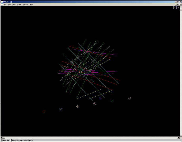
The tracking program can be paused at any frame and allows the user to examine the marker reconstruction geometry. This facility is useful in diagnosing tracking problems and also serves as a very useful teaching tool. The graphics screen displays all rays, calculated marker locations, ray residuals, and predicted marker positions, and allows image manipulation by using use of the mouse. CURRENTLY THIS CAPABILITY IS INCOMPLETE.
Cameras to use
Occasionally it may be useful to exclude one or more cameras from the tracking because a camera is malfunctioning, or you may wish to investigate the contribution of a particular camera on the tracking. The check boxes in this group can be used to ignore data from any camera during the tracking.
ViewSeg
Checking this box causes the ViewSeg to be run automatically after each trial is tracked.
Calibration file
The Calibration file box specifies the folder and name of the calibration file that is to be used for the tracking computations. You may Browse… for it in the Track window of the parameters, or achieve the same result by clicking on the Apply button in the ViewLin widow for the calibration.
ViewSeg
This utility program displays the number and continuity of the segments in a .seg file. The horizontal scale covers all frames in the file, and a segment may display short breaks if the Connect gap feature is enabled in the tracking parameters.
The segments are arbitrarily numbered from the top down according to their order of commencement. The arrow buttons may be used to display segments that do not fit on a single page, and the Next button will display the next .seg file if more than one was selected in the Input files list of the AMASS shell.
Frame diagnostic
Setting the Track parameter Display frame to a valid frame number will case Track to pause processing at the designated frame and allow the user to examine the marker reconstruction geometry. This facility is useful in diagnosing tracking problems and also serves as a very useful teaching tool. The graphics screen displays a 3D view of all rays, calculated marker locations, ray residuals, and predicted marker positions, and allows image manipulation by using use of the mouse. CURRENTLY THIS CAPABILITY IS INCOMPLETE.
The view may be rotated and tilted by use of the left mouse button. The right mouse button allows zooming and changing the lengths of the rays that are displayed. Right double-clicking on a marker makes that marker the center of the display.
AT PRESENT ONLY ONE FRAME CAN BE DISPLAYED IN THE .SEG FILE.
Problem: Ghost markers
The random “ghost” markers that appear from time-to-time can be expected with tracking with that many cameras, but can be almost totally eliminated by setting the tracking parameters to use 3 cameras as the minimum number to use in reconstruction.
With a two camera minimum any accidental ray intersections produce a marker which is very difficult to eliminate without compromising true markers.


