Table of Contents
RT Plugin Motive
Overview
The Motive Plugin is only used in Visual3D Server™. It connects to the Motive software produced by NaturalPoint.
Plugin Interface
The “Plugin Help” button leads to this web page should you need to reference this page in the future.
The “About Plugin” button has details on the plugin being used including version, release date, copy right, support contact information and the hardware SDK version.
Frame Info
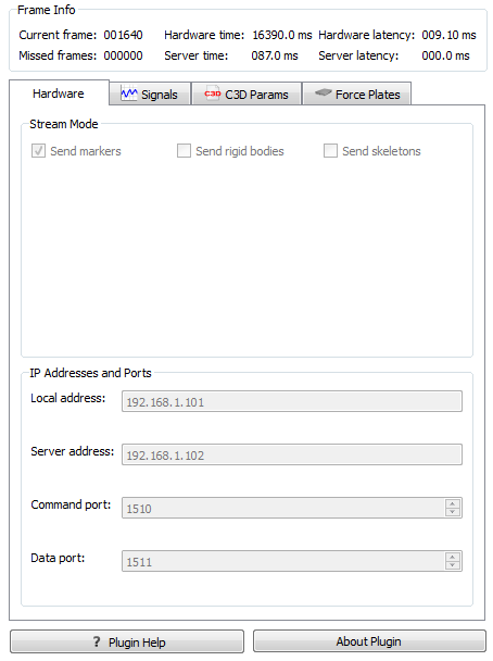
Current frame The current frame number on the top left hand side on the screen (where it currently reads 001640) keeps a count of the current frame which is assigned by the hardware or software system.
Missed frames The missed frames number is on the bottom left (where it currently reads 000000). Whenever there is a gap in frames sent by the hardware of software system a blank frame is inserted. The dropped frames count keeps a record of both the number of frames which are blank.
Hardware time The hardware time number is on the top, in the centre (where it currently reads 16390.0). This time stamp is created by the hardware being used and is how long, in milliseconds, the hardware has been running.
Server time The server time number is on the bottom, in the centre (where it currently reads 087.0). This time stamp is created by the server and is how long, in milliseconds, it has been connected to the hardware or software which is streaming to it.
Hardware latency The hardware latency is on the top right hand side (where it currently reads 009.10 ms). This indicated the delay created by the hardware system.
Server latency The hardware latency is on the top right hand side (where it currently reads 000.0 ms). This indicates any delay introduced by the server.
Hardware
| == Stream Mode == The Stream Mode allows users to chose which type of data is streamed to the server. Data can be sent as individual markers, as rigid body segments constructed in Motive, or as skeletons which are also constructed in Motive. == IP Addresses and Ports == The IP address and Port Number allows Visual3DServer to locate the data that is being broadcast. All four of these need to be set before connecting to Motive. Once the programs are connected the IP address and Port fields will become greyed out and will remain inaccessible until you disconnect the programs. The Local Address is the IP address of the computer running Visual3DServer. The IP addressed used in the example image is 192.168.1.101; Motive does not allow for the “localhost” or 127.0.0.1 shortcuts to be used. The Server Address is the IP address of the computer which is running the Motive software. The IP addressed used in the example image is 192.168.1.102. If you need help finding the IP address of the computer see Trouble Shooting. The Command Port and Data Port numbers are ports which have been chosen by Motive to broadcast data from. The Command Port default is 1510 and the Data Port default 1511. These port numbers can be verified by checking your Motive software. | 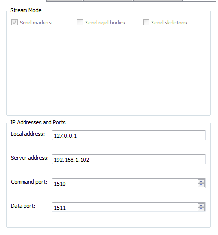 |
Signals
C3D Params
Force Platform
3D View
The right hand side of the screen provides a real-time 3D graphical representation of the data being streamed.
Save 3D View
This button allows you to save what is currently being displayed in the 3D view graphics area. The image can be saved in a number of standard formats, such as .bmp, .ico, .jpeg, .jpg, .pbm, .pgm, .png, .ppm, .tif, .tiff, .wbmp, .xbm, or .xpm. This function is ideal for producing graphics for papers or presentations. Saved images can be edited with 3rd party graphics programs if needed.
Copy 3D View to clipboard
This button allows you to copy what is currently being displayed in the 3D view graphics area to the clipboard. This allows you to paste the image into any program that supports copy and paste. This is useful for working with presentation or graphics editing software.
Reset camera 3D View
This button brings the 3D viewer back to it's beginning position. You may find that having used the rotation, translation, and zooming capabilities of the 3D view you have lost track of where you are in the graphics, which can make returning to a proper view of your data challenging. The reset view button removes this frustration and reorients you.
3D View Preferences
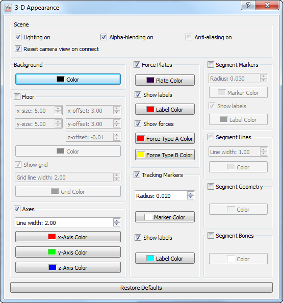
This button allows you to change how the graphics that are presented to you. Changes happen in real time. At the bottom is the “Restore Defaults” button which resets all of the options to their standard setting.
= Scene =
Lighting on - When selected graphics that are suppose to be 3 dimensional have shadows to help simulate shape. When not selected objects are one solid color.
Reset camera view on connect - When this box is selected and you connect or reconnect to hardware the camera view will reset to it's default.
Alpha-blending on - When this box is selected the graphics are slightly transparent and allow you to see what is behind them
Anti-ailiasing on - When this box is selected all the lines in the graphics are smooth. If it is not selected the lines that are not either horizontal or vertical change directions portion by portion.
= Background =
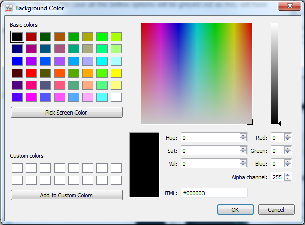
Color - This allows you to change the background color to anyone you chose.
= Floor =
When the check box next to the floor is not checked the floor will not appear in the 3D View. In this case all the bellow options will be greyed out as they will have no effect if the floor is not present.
X-size - This allows you to customize how many panels the floor is composed of in the x direction. the minimum is 1 and maximum is 100. The default size is 5.00.
Y-size - This allows you to customize how many panels the floor is composed of in the y direction. the minimum is 1 and maximum is 100. The default size is 5.00.
X-offset - This allows you to shift the entire floor along the x-axis either in the positive or negative direction. The maximum value allowed is 100 and the minimum value is -100. The default setting is 3.00.
Y-offset - This allows you to shift the entire floor along the y-axis either in the positive or negative direction. The maximum value allowed is 100 and the minimum value is -100. The default setting is 3.00.
Z-offset - This allows you to shift the entire floor along the z-axis either in the positive or negative direction. The maximum value allowed is 100 and the minimum value is -100. The default setting is -0.01.
Color - This allows you to change the floor color to anyone you chose.
Show grid - This allows you to remove the grid lines from the floor by unchecking the checkbox.
Grid line width - This allows you to change the thickness of the gridlines. The minimum value is 1 and the maximum value is 10. The default width is 2.00.
Grid color - This allows you to change the grid line color to anyone you chose.
= Axes =
When the check box next to the axis is not checked the axis will not appear in the 3D View. In this case all the bellow options will be greyed out as they will have no effect if the axis is not present.
Line width - This allows you to change the thickness of the axis lines. The minimum value is 1 and the maximum value is 10. The default value is 2.00.
X-Axis Color - This allows you to change the x-axis line color to anyone you chose.
Y-Axis Color - This allows you to change the y-axis line color to anyone you chose.
Z-Axis Color - This allows you to change the z-axis line color to anyone you chose.
= Force Plates =
When the check box next to the force plates is not checked the force plates will not appear in the 3D View. In this case all the bellow options will be greyed out as they will have no effect if the force plates are not present.
Plate Color - This allows you to change the force plate color to anyone you chose.
Show labels - This allows you to remove the force plate label, (such as FP1, FP2 . . . etc) from the 3D view.
Label Color - This allows you to change the force plate label color to anyone you chose.
Show forces - When checked the forces will be show in the 3D view using arrows.
Force Type A Color - This allows you to change the color of the raw force arrows to anyone you chose.
Force Type B Color - This allows you to change the color of the force structure arrows to anyone you chose.
= Tracking Markers =
When the check box next to the tracking markers is not checked the tracking markers will not appear in the 3D View. In this case all the bellow options will be greyed out as they will have no effect if the tracking markers are not present.
Radius - This allows you to change the radius of the markers. The maximum value is 0.100 the minimum value is 0.001. The default radius is 0.020.
Marker Color - This allows you to change the color of the marker color to anyone you chose.
Show Labels - This allows you to remove the marker labels from the 3D view.
Label Color - This allows you to change the color of the label to anyone you chose.
= Segment Markers =
When the check box next to the segment markers is not checked the segment markers will not appear in the 3D View. In this case all the bellow options will be greyed out as they will have no effect if the segment markers are not present.
Radius - This allows you to change the radius of the markers. The maximum value is 0.100 the minimum value is 0.001. The default radius is 0.020.
Marker Color - This allows you to change the color of the marker color to anyone you chose.
Show Labels - This allows you to remove the marker labels from the 3D view.
Label Color - This allows you to change the color of the label to anyone you chose.
= Segment Lines =
When the check box next to the segment lines is not checked the segment lines will not appear in the 3D View. In this case all the bellow options will be greyed out as they will have no effect if the segment lines are not present.
Line Width - This allows you to change the thickness of the segment lines. The minimum value is 1 and the maximum value is 10. The default value is 1.00.
Color - This allows you to change the color of the segment lines to anyone you chose.
= Segment Geometry =
When the check box next to the segment geometry is not checked the segment geometry will not appear in the 3D View. In this case all the bellow options will be greyed out as they will have no effect if the segment geometry is not present.
Color - This allows you to change the color of the segment geometry to anyone you chose.
= Segment Bones =
When the check box next to the segment bones is not checked the segment bones will not appear in the 3D View. In this case all the bellow options will be greyed out as they will have no effect if the segment bones are not present.
Color - This allows you to change the color of the segment bones to anyone you chose.

