Table of Contents
ANALOG Data Type
Historically in Visual3D and as mandated by the C3D file format, analog signals are one-dimensional signals (e.g. contain one element per time frame) that are all sampled at the same rate; the ANALOG rate must be an integer multiple of the POINT rate.
Common ANALOG Parameters
Common parameters that Visual3D expects to be in the ANALOG Section of the C3D File.
| GEN_SCALE | Scaling factor that is multiplied by the Analog_Scale factors that are applied to every signal |
| RATE | The sampling rate of the ANALOG data |
| SCALE | A scaling factor for each signal that is multiplied by the Analog_Gen_Scale and applied to each signal. |
| OFFSET | an offset for each signal that is subtracted from each signal before the signal is scaled. |
| USED | The number of signals containing ANALOG data |
| LABELS | The Label Names of the ANALOG data signals |
| DESCRIPTIONS | The Descriptions of the ANALOG data signals. This information is rarely used by Visual3D. |
| FORMAT | For integer data declares 12 bit or 16 bit data |
| UNITS | The Units in which the ANALOG data signals are stored in the file. The default value is v (Volts) |
| BASELINES | Used by Visual3D to define a baseline to be subtracted from each analog signal after the SCALE and OFFSET are applied. This value is typically computed during Real_Time streaming of the data. |
Other Parameters will be read by Visual3D but only in special circumstances will they be used.
The BASELINES parameter was introduced by C-Motion to accommodate Real-time streaming data. For streaming data there is no frame number from which to define a range for the ZERO parameter. This doesn't mean that the ZERO parameter should be ignored.
In Visual3D streaming there is a button to starting the ZERO range. In order to replicate the data for post-processing these baselines need to be saved with the C3D file and the ZERO parameter set to 0,0.
Modify_Analog_Parameters
This command can be used to change a selection of the ANALOG parameters in a C3D file. There must be the same number of values in the LABELS, SCALE, and OFFSET entries. The command will modify the parameters in order. For example, if two entries are specified, the first two entries in the ANALOG parameters will be modified; the remaining parameters will remain the same.
| Modify_Analog_Parameters | |
| /Analog_Labels= | Enter the new Analog Labels in the order that they appear in the c3d file ANALOG PARAMETERS. |
| /Analog_Gen_Scale= | Enter a scaling factor that is multiplied by the Analog_Scale factors that are applied to every signal. |
| /Analog_Scale= | Enter a scaling factor that is multiplied by the Analog_Gen_Scale and applied to each signal. |
| /Analog_Offset= | Enter an offset for each signal that is subtracted from each signal before the signal is scaled. |
| /Update_C3D_File= | (True or False) Update the C3D file on disk automatically. |
| ; |
Note: The ANALOG labels are part of the C3D file, so updating the labels also updates the C3D ANALOG:PARAMETERS:LABELS section.
If the Analog_Scale or Analog_Labels parameter have fewer entries in the command than signals in the file, only the number parameters specified will be processed. In the order that the signals appear in the C3D PARAMETERS section of the file
For example, if only one Analog_Labels parameter is specified in the command, only the first Analog_Label will be modified.
Examples
Some manufacturers store ANALOG signals with labels that have no inherent meaning. For example, A001, A002, etc. These labels can be renamed using Modify_Analog_Parameters pipeline command. The example below will rename the first two analog signals to RecFem and Gastroc.
Modify_Analog_Parameters
/ANALOG_LABELS=RecFem+Gastroc
! /ANALOG_GEN_SCALE=
! /ANALOG_SCALE=
! /ANALOG_OFFSET=
! /ANALOG_BASELINE=
! /UPDATE_C3D_FILE=TRUE
;
The example below will modify the SCALE to 1.0 for the first 5 Analog Signals and automatically save the file to disk. No other Analog parameters will be modified.
Modify_Analog_Parameters
! /ANALOG_LABELS=
! /ANALOG_GEN_SCALE=
/ANALOG_SCALE= 1.0+1.0+1.0+1.0+1.0
! /ANALOG_OFFSET=
! /ANALOG_BASELINE=
! /UPDATE_C3D_FILE=TRUE
;
The /Analog_baseline parameter will accept expressions. The example below will modify the baseline value for the first analog signal using a metric signal METRIC::PROCESSED::OFFSET
Modify_Analog_Parameters
! /ANALOG_LABELS=
! /ANALOG_GEN_SCALE=
! /ANALOG_SCALE=
! /ANALOG_OFFSET=
/ANALOG_BASELINE=METRIC::PROCESSED::OFFSET
! /UPDATE_C3D_FILE=FALSE
;
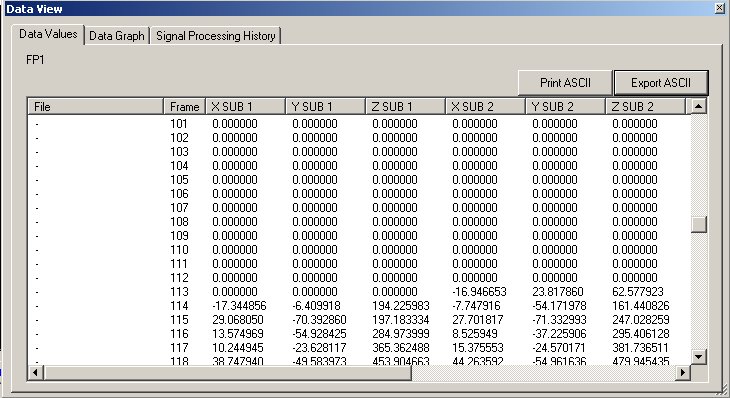
Visual3D Data View dialog displaying an ANALOG signal
The first column of each component in the row in the data window is displayed at the Motion Capture rate. If the ANALOG signals are collected at a higher rate, which is usually the case, then there are multiple values of the ANALOG signal for each motion capture frame. The column headings SUB1 etc refer to the subframes with respect to the motion capture rate.
For example, in the figure above, the first three columns of data are the x,y,z components of the Analog frame that is synchronous with the video frame. The next 3 columns are a sub frame (e.g. the additional frames because there are more analog samples than video samples).
Conventional C3D Representation of ANALOG Signals
ANALOG signals are stored as either INTEGERS with OFFSET and SCALING factors or as REAL (FLOAT) values with SCALING factors. After scaling the ANALOG signals should be stored as, VOLTS. This means that the ANALOG ORIGINAL signals in the Visual3D data tree are usually in volts.
Exceptions to this rule are usually related to ANALOG data from force platforms. Type 1 and Type 2 force platforms for example store data in Newtons, or Newton-millimeters. This has changed in recent years as calibration matrices are now commonly stored as a C3D parameters, so the ANALOG signals are left in volts.
ANALOG data stored as integer values.
ANALOG data stored as integers are assumed to be UNSIGNED INTEGERS unless the parameter ANALOG:FORMAT is set to SIGNED
For ANALOG INTEGER data.
ANALOG:OFFSET
12 BIT A/D has an offset of 2047 UNSIGNED INTEGERS
16 BIT A/D has an offset of 32767 for UNSIGNED INTEGERS
ANALOG:SCALE for scaling A/D data to volts
For most signals the value S would be the scaling factor stored in the C3D file.
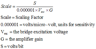
An exception are force platform data that is derived from strain gauges, which require an additional scaling based on the bridge excitation and amplifier scaling. The Scaling parameter stored in the C3D file would be:
Note: Analog signals from force platforms are usually NEGATIVE in the C3D file.
For example ANALOG data collected using a 16 bit A/D board with a plus/minus 10 volt range. Set:
ANALOG:GEN_SCALE=0.000305017
In addition, a type 4 force platform in which the excitation voltage=10 and the amplifier gain=4000
Set the scale for each force platform channel
ANALOG:SCALE=-25 for each channel
For all other ANALOG channels set the scale to
ANALOG_SCALE=1 for each channel
Examples
Combining 3 analog signals into a vector
This example will create a vector named Vector from 3 analog signals. This is an example of merging 3 signals into one signal.
Merge_Data
/SIGNAL_NAMES=Analog1+Analog2+Analog3
/SIGNAL_TYPES=ANALOG+ANALOG+ANALOG
/SIGNAL_FOLDER=ORIGINAL+ORIGINAL+ORIGINAL
/SIGNAL_COMPONENTS=0+0+0
/RESULT_NAME=Vector
/RESULT_TYPE=DERIVED
/RESULT_FOLDER=PROCESSED
/MERGE_TYPE=MERGE_AS_NEW_COMPONENTS
;
alternatively,
Evaluate_Expression
/EXPRESSION=VECTOR(ANALOG::ORIGINAL::Analog1,ANALOG::ORIGINAL::Analog2,ANALOG::ORIGINAL::Analog3)
! /RESULT_TYPES=DERIVED
! /RESULT_FOLDERS=PROCESSED
 /RESULT_NAME=NewVector
! /APPLY_AS_SUFFIX_TO_SIGNAL_NAME=FALSE
;


