Table of Contents
Landmark Types
Landmarks provide a powerful method of representing significant locations within space or locations defined by the model. Landmarks are created by either specifying a location in a segment coordinate system or by transforming markers or other landmarks into a significant location.
Landmarks are like virtual markers, whose positions are computed automatically by Visual3D based on the positions of the actual markers, segments, or equations, according to rules which you define.
The landmark mechanism is the key to Visual3D’s highly flexible modeling capabilities. A single example suffices to suggest the usefulness of markers. Frequently, target markers are mounted on short posts which protrude away from the skin surface, and consequently, defining a segment using medial and lateral markers as described above will tend to over-estimate the segment’s radii. You can eliminate this problem by creating landmarks which are like “shadow versions” of the actual markers, moved inward by the length of the marker posts to better approximate the skin surface, and then define your segments based on these landmarks.
Pipeline Commands
If you want to create a landmark using a pipeline command and you already know how to create the landmark interactively in Model Builder Mode, you can save the model template to disk. Open the model template and search for the Landmark definition. You can then cut-and-paste the definition into a pipeline. The only difference will be that you must specify the Model that is to be used; e.g. the model template already defines which model is to be used to create the landmark.
Landmark Extent
Landmarks can be 'calibration only' or can be calculated for the motion files.
Calibration Only
Used only for segment calibration, but are not needed (or produced) for any associated motion file(s).
Generated for Assigned Motion Files
Generated for the calibration file, and the associated motion files. These landmarks may be used for tracking a segment.
Landmark Types
There are several landmark types or ways to create landmarks. Landmarks can be created:
- as a point relative to one marker/landmark
- as a point on a Line
- as a point in a Plane
- as a point Projected on a Line
- as a point Projected on a Plane
- as offsets
- relative to segments
- digitized with a pointer
- as a functional point
- to create muscles which are defined by linear segments connecting a series of Landmarks.
Point Projected on a line
Point projection onto a line can be used at the shoulder to project a lateral target on to a vertical line passing through the acromium or it can be used at the knee to project lateral or medial targets on a functional axis.
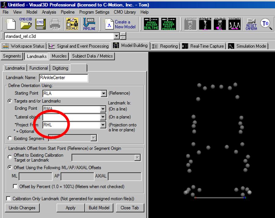
To define a landmark as a point projected on a line (two other points define a line in space), select the Targets and/or Landmarks radio button. Select 2 targets and/or landmarks for the Reference/Axial Starting Point and Axial Ending Point. Select a point to project using the Projected From combo box.
In the image below, the RAnkleCenter is the point that is created by projecting the RHL heel marker onto the line created from the lateral and medial ankle markers RLA and RMA.
Another example can be found on this page, Project onto a line.
Point Projected on to a plane
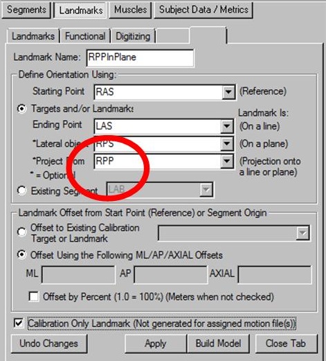
By projecting multiple landmarks onto the same plane you can build segment coordinates systems in a specific plane. To define a landmark as a point projected onto a plane defined by 3 points, select the Targets and/or Landmarks radio button. Select three targets and/or landmarks for the Reference/Axial Starting Point, Axial Ending Point and Lateral object to define a plane. Select a point to project using the Projected From combo box.
In the image below, the RPPinPlane is the point that is created by projecting the RPP marker on the illiac crest onto the plane created from the right and left ASIS's (RASI,LASI) and the right PSIS RPS marker.
Example 1: Project the hip joint onto a plane passing through the GT's
This example will illustrate how one would project a hip joint center landmark onto frontal plane of the pelvis passing through the greater trochanters.
Example 2: Project onto a principal plane
This is an example of how one would project a heel marker, RHEEL on the floor or X-Y plane of the laboratory.
Offsets
Landmarks are often offsets from existing target markers. The origin of the offset is the starting point (reference point). The offset is specified as an absolute distance in meters, or as a percentage. The percentage is relative to a segment or markers.
Use regression equations as offset
One can use regression equations as an offset in the landmark definition (i.e. Hip joint centers) see the example in the previous section Example 1: Project the hip joint onto a plane passing through the GT's.
= Hip Landmark =
Landmarks defining the location of the hip joint center are not particularly notable except that two of the default Pelvis segment types (Coda and Helen Hayes) create hip joint landmarks automatically when the segment is created.
= Bell and Brand Hip =
Specifying the Hip Joint Landmark using Bell and Brand. This page will also illustrate how to create a generic pelvis technical coordinate system and hip landmarks.
= Hip Landmark from Custom Regression Equation =
Specifying the Hip Joint Landmark using a custom regression equation
Relative to a segment
Landmarks can be created relative to a segment (in the segment coordinate system).
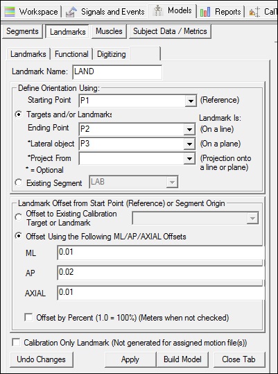
To define a landmark in a segment coordinate system, in the Landmarks Mode, select the Existing Segment radio button, and select a segment in the existing segment combo box below the button. Segment landmarks are, by default, offset from the segment origin. If you would like to offset the landmark from a different location you must select a Reference/Axial Starting Point marker/landmark location. The landmark offsets can be specified in any coordinate system that has been defined in the model. When defining a landmark relative to a segment, the 3 components of the offset are defined anatomically as ML, AP, and AXIAL boxes.
If you would like to offset the landmark in lab space, you may select the LAB segment in the existing segment combo box. When the landmark is relative to the LAB the offsets are the X, Y and Z directions of the lab.
= Landmark relative to a thigh segment =
This is an example of creating a landmark relative to a thigh segment with ML, AP, and AXIAL offsets in percent.
= Landmark at segment endpoint =
Creating a landmark at the end of a segment that is tracked with the segment
= Example using a reference location =
This example creates a landmark relative to a segment (or to 3 markers) using a reference location.
Relative to 3 Locations
Landmarks can be created relative to 3 locations. This can be handy when removing markers in the motion trials.
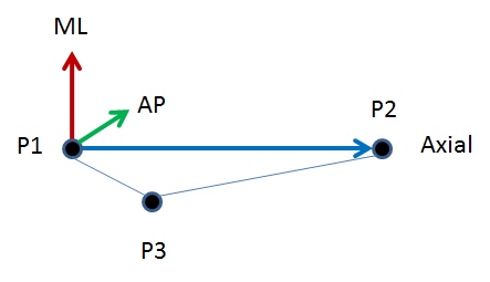
A right handed orthogonal coordinate system is defined by the three points (P1, P2, P3).
The origin of the coordinate system is at the point P1
The frontal plane of the coordinate system is defined by the three points.
The positive AP direction is into the screen.
Landmark Type 5
Create a landmark defining the location of a segment endpoint relative to 3 tracking markers (or landmarks).
Digitized Landmarks
The objective for using the pointer is to identify anatomical landmarks without having to place motion capture markers at the location.
Functional Landmarks (Joints)
The functional joint calculations have been adapted from:
Schwartz MH, Rozumalski A (2005) A new method for estimating joint parameters from motion data. Journal of Biomechanics, 38, 107-116] and from Jensen E, Lugade V, Crenshaw J, Miller E, Kaufman K (2016) A principal component analysis approach to correcting the knee flexion axis during gait. Journal of Biomechanics, in press]
Muscles
Muscles are defined by linear segments connecting a series of Landmarks. The Landmarks can be created using any of the rules for creating landmarks in Visual3D.
Examples
Create a Landmark Mimicking contralateral segment
It was not possible to place anatomical landmarks on the medial and lateral ankle of the subject because the subject was missing one lower limb. It was possible to place markers on the foot prosthesis consistent with the existing foot. Assuming symmetry in the two foot segments the user wanted to create landmarks representing the location of the medial and lateral ankle of the missing shank relative to the foot coordinate system consistent with the location of the medial and lateral ankle in the existing segment.
Create Landmarks from a Knee Alignment Device
The Knee Alignment Device (KAD) is manufactured by Motion Lab Systems. The KAD is used to assist in defining the frontal plane of the thigh segment. This page describes the KAD and shows how it is implemented to create the frontal plane and landmarks in Visual3D.
Create a Landmark Using two standing trials
Landmarks can be created from two static standing trials.
Replacing missing landmark
We collected 2 sets of studies for the same person, and we collected one static trial of the lower extremity for each set of the study. We forgot to add the GT markers for the first static trial. Based on what we have right now (a complete 2nd static trial and the 1st static trial with GT markers missing), is it possible for us to create a virtual GT marker for the first static trial?
Create a Landmark for a Missing Tracking Marker
Landmarks can be created to calculate missing tracking markers.
Example: Missing Tracking Marker in Static Trial
Consider the following right thigh segment constructed using static markers RPPT, RAPT, RPDT, RADT. These tracking markers are saved to a model template, but for the next subject the static trial is missing the RAPT marker. A landmark can be created to replace the missing tracking marker.
Create Landmarks from Motion Trial
Landmarks can be created from the motion trials.
Using Motion Trial Example 1
This example creates landmarks from Targets in a movement trial but not in the standing trial. In this example, a movement trial contains 4 markers that have been placed on the corners of an object. The standing trial does not contain these markers, but needs the corner locations for defining an object (segment).
Using Motion Trial Example2
A structure (i.e. stairs) can be defined by placing markers at vertices, then connecting these vertices. It isn't always practical, however, to place these markers during the standing trial, so it would be useful to have a separate motion trial that contained only these markers. In this example, we demonstrate how to get the marker locations from a movement trial and create landmarks. In the movement trial for this example, markers are placed on the steps of a set of stairs.


