Table of Contents
Constructing the Segment Coordinate System
To measure the motion of anatomical segments, the fixed A for each tracking target must be known. Visual3D uses a static subject calibration trial to establish locally fixed SCSs and subsequently find the fixed A for each tracking target.
An alternate version of this tutorial can be found here.
Segment Endpoints
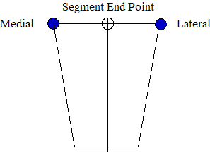
Definition of the proximal or distal end point of a segment is usually done by placing markers near the endpoint of the segment and using one of the following methods. Note that many other methods might be used.
Method 1
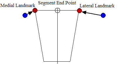
Method 2
If the motion capture markers are not located on the anatomical landmarks because, for example, a lesion or a brace is already at that location, a landmark can be used instead.
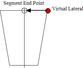
Method 3
In some cases it is desirable to use only a lateral marker and an offset.
Establishing an Anatomical Plane
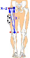
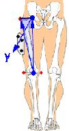
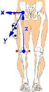
The first step in creating a local SCS is the establishment of the frontal plane. Visual3D allows the user to place either one or two border targets at each end of the segment during subject calibration. (The border targets can be of the type MED_DIST, MED_PROX, LAT_DIST and LAT_PROX) Thus the SCS can be created using two targets (a single border target at each end & an extra target to define orientation), three targets (two border targets at one end and a single border target at the other) or four targets (two border targets at each end).
Figure 1
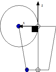
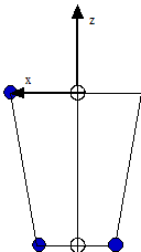 | Figure 1. If three border targets are used then the frontal plane is simply the plane define by the three targets. |
Figure 2
Figure 3
While it is possible to define a segment with only two targets, we strongly encourage that each segment requires at least three calibration targets that are used to locate the proximal and distal joint centers and define the frontal plane of the LCS. The two target case can be transformed to a three target case by explicitly creating a virtual target from one of the two targets. In this way the user has explicitly defined the frontal plane and will not be surprised by the results.
Establishing the Segment Ends
After creating the frontal plane, Visual3D then establishes the distal and proximal segment ends. It should be noted that for kinetic computations, the joint center is assumed to be at the proximal end of the segment distal to the joint. If three border targets are used on a segment, Visual3D creates one segment end at the midpoint between the medial and lateral targets. At the opposite end, where only a single border target is used, Visual3D first defines a circle in the frontal plane (SCS XZ plane) at a distance of one radius from the border target. Visual3D then establishes the segment end to be the point on the circle such that the vector from that end to the border target will be perpendicular to the vector connecting the two segment ends (Figure 2). If four border targets are used then the midpoints between medial and lateral targets are used to define each end of the segment (Figure 2). If only two border targets are used then, each segment end is established by translating the border one radius along the V3CS X axis (Figure 2). NOTE: this translation is along the V3CS X axis and not along the X axis of the users LCS (see Chapter 13 regarding the relationship between the V3CS and the LCS).
Establishing the SCS X, Y and Z Axes
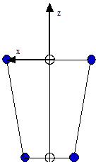
The SCS Z axis is determined by the unit vector directed from the distal segment end to the proximal segment end. Next, the SCS Y axis is determined by the unit vector that is perpendicular to both the frontal plane and the Z axis. Finally, the SCS X axis is determined by the application of the right hand rule. From the above discussion it can be seen that, the SCS Z axis is directed from distal to proximal, the SCS Y axis is directed from posterior to anterior, and the SCS X axis is medial-lateral in orientation.
Establishing the Origin of the SCS
The SCS origin is located along the line connecting the segment ends (the SCS Z axis) at the segment's proximal joint.
Step-By-Step Procedure
 | Step 2. The z-axis is defined by the vector from the distal segment endpoint to the proximal segment endpoint. |
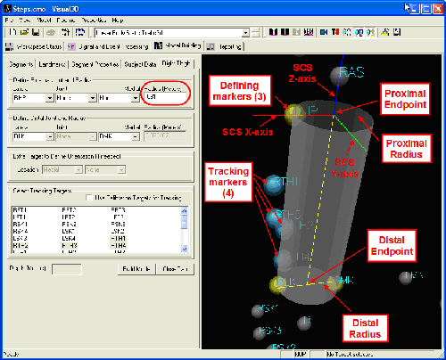
The illustration above shows what you might see when defining just one segment—the right thigh. The graphic image, which is zoomed in to the right thigh region, reveals three calibration markers (yellow) which are used to define the thigh segment’s endpoints and dimensions. At the proximal (upper) end, the RHP (right hip) marker’s position is used together with an explicit radius of 0.081m (measured in the laboratory for this subject) to define the proximal endpoint. At the distal end, both medial and lateral knee markers (RMK, RLK) are available, and together define both the distal endpoint and the distal radius of the thigh segment. For mass- and moment-related computations, this segment is modeled as a truncated cone (this is one of many details you provide under the Segment Properties tab) and so both proximal and distal radii are needed.
Modifying the Segment Coordinate System
There are times in which it is useful to modify the segment coordinate system after the segment has been created. Usually this happens when you want to preserve the segment length from the original construction of the segment, but now need to align the segment coordinate system with another segment coordinate system. See this topic

