Table of Contents
Helen Hayes (Davis) Pelvis
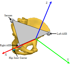
The Helen Hayes pelvis refers to a pelvis segment model defined by Davis et. at. (1991) and used by many manufacturers, including the VCM model by Vicon. The pelvis segment is defined using the anatomical locations of the ASIS (Anterior Superior Iliac Spine) and the midpoint between the PSIS (Posterior Superior Iliac Spine) commonly referred to as the Sacrum marker. These landmarks are bony protuberances on the Pelvis bones that can be palpated on most (but not all) subjects. There are particularly useful if the subject is very thin, a cadaver, or a skeleton, and historically have been the reference points for defining the segment coordinate system for many experimental studies focused on determining regression equations for locating the hip joint centers. Unfortunately, these landmarks are not easily palpated, or more importantly, cannot have motion capture markers placed accurately on them, for overweight subjects. This challenge notwithstanding, the CODA pelvis and HELEN HAYES pelvis segments are still popular in many laboratories.
Pelvis Origin
The origin of the segment coordinate systems is defined as the mid-point of the right and left ASIS markers. As declared below, we have used a least squares fit to determine the orientation and this will move the origin slightly.
Pelvis Orientation
The orientation of the coordinate system is defined by a plane passing through the right and left ASIS markers, and the sacrum marker (mid-point of the PSIS) as follows:
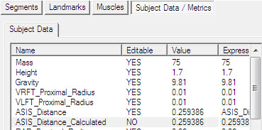
Compute the ASIS_Distance Compute the Depth as the distance from the origin to the Sacrum marker. The coordinates of the three markers in the pelvis coordinate system are assumed to be: Right Asis= (0.5*ASIS_DISTANCE,0,0) Left Asis= (-0.5*ASIS_DISTANCE,0,0) Sacrum=(0,-DEPTH,0) The coordinate system is then computed as a least squares fit of the three local coordinates to the three actual coordinates using the same algorithm as the 6 degree of freedom pose estimation described elsewhere in this documentation.
Orientation Comments
This definition of the orientation is different than the implementation for the Coda pelvis. The Coda pelvis definition (e.g. using cross products) is more common, but we didn't realize this until several years after the Helen Hayes pelvis was introduced in Visual3D. Once this definition had been used by customers for several years it was not possible to “change gears” and modify the definition, so we left it as is.
Customers that want a different definition should use the Coda pelvis, and if necessary, add expressions to the hip landmarks to mimic the Helen Hayes hip definition.
Is this the original specification of the Davis pelvis?
While it was our intention to be consistent with the Davis pelvis when we implemented this originally, it is not actually equivalent because we have used a least squares fit instead of cross products. If you want to re-create the Davis pelvis, it is advisable to use the Composite pelvis and modify the location of the hip joint landmark.
Hip Joint Center
If no clinical measurements are taken, the following values are calculated:
Leg Length= 0.5*(Right Leg Length + Left Leg Length). Right Leg Length= distance from Right ASIS to Right Lateral Ankle Left Leg Length= distance from Left ASIS to Left Lateral Ankle Notes: (1) If unilateral data is collected Leg Length= Length of that Leg. (2) If the lateral ankle is not used to define the foot segment, the ankle joint center is used instead. ASIS_distance= 3D distance between ASIS markers Bilateral anteroposterior distance= 0.1288*Leg Length-0.04856 Estimates for the Right and Left Hip Joint Center are represented as Landmarks that are created automatically when the Helen Hayes pelvis segment is created. The location of the landmarks are defined in the Pelvis Segment Coordinate System as:
| Hip X= | -S (C sin(theta)-0.5*ASIS_distance) |
| Hip Y= | (-Xdis-Rmarker) cos(beta)+ C cos(theta) sin(beta) |
| Hip Z= | (-Xdis-Rmarker) sin(beta)- C cos(theta) cos(beta) |
| Where: | |
| C= | 0.115*LegLength - 0.0153 (in meters) |
| theta= | 28.4*PI/180.0 |
| beta= | 18.0*PI/180.0 |
| ASIS_distance= | ASIS to ASIS distance, measured during clinical exam |
| Xdis= | anterior/posterior component of the ASIS/hip center distance in the sagittal plane of the pelvis and measured during the clinical exam |
| If Xdis not measured: | |
| Xdis= | 0.1288*LegLength - 0.04856 |
| Rmarker= | marker Radius (in meters) |
| S= | +1 for the right side and -1 for the left side |
These equations are adapted from the article:
Davis RB, Ounpuu S, Tyburski D, Gage JR. (1991) “A Gait Analysis Data Collection and Reduction Technique.” Human Movement Science, 10: 575-587.


