Table of Contents
Pelvis Overview
There are many ways to define a segment in Visual3D, which means there are many ways to define a Pelvis segment.
A pelvis segment can be constructed as any other segment, and so the default pelvis segment in Visual3D is labeled a Visual3D Pelvis. Visual3D inherited this definition from MOVE3D (the precursor software to Visual3D) and has been used by the staff in the Physical Disabilities Branch at the NIH for more than 20 years.
Visual3D has two other Pelvis types in Visual3D that share the same resultant segment coordinate system, but each has associated regression equations that define the location of the Hip Joint Centers (defined in the Pelvis segment coordinate system).
Choosing between Helen Hayes and CODA Pelvis
I usually recommend choosing the CODA Pelvis within Visual3D mostly because it does not require an estimate of the Leg Length, which can be a bit of a problem for some patients. The CODA pelvis also does not require the measurement of the ASIS-greater trochanter distance, which I find that very few laboratories ever make.
For the CODA/DAVIS pelvis the segment coordinate system typically will be tilted forward about 20 degrees forward. It is possible, however, to create a Visual3D pelvis from this same data set such that the pelvic tilt matches the clinical measure of pelvic tilt.
Creating Visual3D Pelvis from Coda Pelvis
The Visual3D pelvis is created typically using Iliac Crest markers and Greater Trochanter markers. The Conventional Gait marker set, however, does not include these markers. One of the consequences of creating a CODA/DAVIS pelvis, however, is that Hip Joint Centers are created automatically based on regression equations.
The following process can be used to create a Visual3D pelvis segment coordinate system using the Conventional Gait marker set.
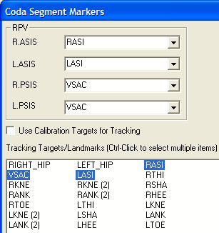
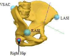
First, create a CODA pelvis and note the creation of Hip Joint Landmarks.
Remove the animation model associated with the CODA pelvis. Switch to the Segment Properties tab and remove the assignment to the obj and col files.
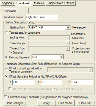
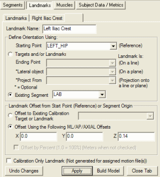
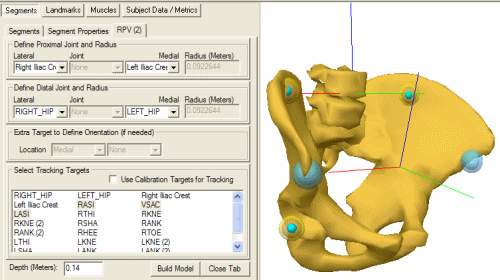
Create landmarks to represent the location of the Iliac Crest markers. In this example, I elected to have a segment coordinate system aligned with the laboratory, resulting in a pelvic tilt of zero degrees. Modifying the location of the landmarks will allow the creation of any orientation.
Create the Visual3D Pelvis
Note the difference in orientation of the two pelvis segment coordinate systems.
The previous process created a pelvis segment coordinate system that was aligned vertically by creating landmarks located vertically above the hip joint centers. Any pelvic tile, however, can be created by a modest change to the landmark definitions.
Note: Visual3D allows the use of mathematical expressions in most of the edit boxes in model builder model. In the previous section the following landmarks were created.
Landmark Name=Right Iliac Crest
Starting Point=RIGHT_HIP
Offset Using the Following ML/AP/AXIAL Offsets= Checked
X=0.0
Y=0.0
Z=0.19
Landmark Name=Left Iliac Crest
Starting Point=LEFT_HIP
Offset Using the Following ML/AP/AXIAL Offsets= Checked
X=0.0
Y=0.0
Z=0.19
Assuming the y-direction is Anterior. We can create a forward tilt of the pelvis of 0.3 radians by modifying the landmarks as follows:
Landmark Name=Right Iliac Crest Starting Point=RIGHT_HIP Offset Using the Following ML/AP/AXIAL Offsets= Checked X=0.0 Y=0.19*sin(0.3) Z=0.19*cos(0.3) Landmark Name=Left Iliac Crest Starting Point=LEFT_HIP Offset Using the Following ML/AP/AXIAL Offsets= Checked X=0.0 Y=0.19*sin(0.3) Z=0.19*cos(0.3)

