Table of Contents
Export Polygon Trunk Example
Polygon Trunk
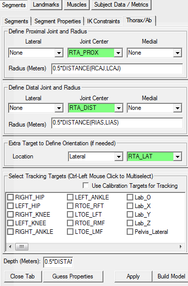
The proximal end of the trunk is often defined as the shoulders and the distal end is at the waist[1]. This definition will be referred to as “Typical Convention” in the following documentation.
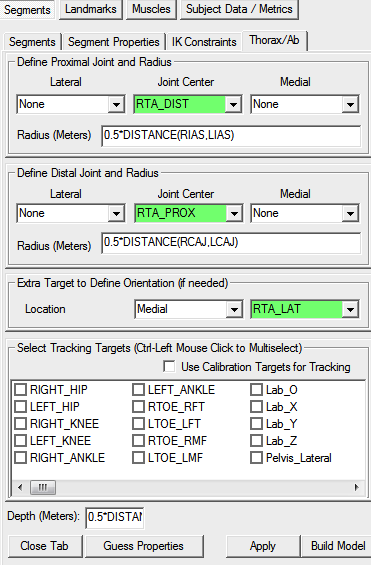
The Polygon definition uses the waist as the proximal end and the shoulders as the distal. This definition will be referred to as “Polygon Convention” in the following documentation.
Important NOTE: Visual3D is marker set independent, and even when using the Polygon requirements to define the trunk, there are still MANY ways to define the trunk segment. This tutorial is NOT a recommendation for how to define the trunk segment.
The sample files can be downloaded here. A sample script to export signals to Polygon can be found in the zip file.
Typical Convention
A CMO file where the trunk is defined using “Typical Convention” can be downloaded here. The file “SampleWorkspace_Typical.cmo” contains the trunk described below.
Polygon Convention
A CMO file where the trunk is defined using the “Polygon Convention” can be downloaded here. The file “SampleWorkspace_Polygon.cmo” contains the trunk described below.
Coordinate System Orientation
If the segment has been defined correctly, the origin should be just below the ribs. The orientation of the segment coordinate system should be aligned with the coordinate systems of the other segments in the model. In the image, the coordinate systems was rotated so that +Z is up and +X is mediolateral. Instructions to rotate a coordinate system can be found here. |  |
Skeleton
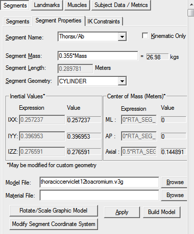
The default image for the thorax/ab segment includes the lumbar. Since these segments are not included in the Polygon convention, you may want to modify the graphic image in the Segment Properties tab. Please note, this is only for aesthetics.
References
- ↑ Serge van Sint Jan “Color Atlas of Skeletal Landmark Definitions: Guidelines for Reproducible Manual and Virtual Palpations” 2007 - Churchill Livingstone: p. 3


