Importing Aurora Files
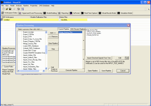
Merge_Aurora_Files
! /INPUT_FILE_NAMES=
! /OUTPUT_FILE_NAME=
! /FRAME_RATE=1000
! /UNITS=cm
! /SET_PROMPT=Open Aurora files
;
Given Aurora files in which each signal is stored independently in an ASCII file with the following format.
Collection Data : Port 01 ( Traxtal Tech S/N: 343BBC0E Type: 01000000 Rev: 000 ) [August 17, 2002 02:16AM]
| Frame, | Q0, | Qx, | Qy, | Qz, | x, | y, | z, |
| 1369560, | 0.2980, | -0.6755, | 0.2496, | -0.6264, | 97.82, | 56.54, | -102.57, |
| 1369592, | 0.2980, | -0.6755, | 0.2496, | -0.6264, | 97.82, | 56.54, | -102.57, |
The variables are described in the NDI Aurora Manual. Q0, Qx, Qy, Qz represent the orientation expressed as a Quaternion X, Y, Z represents the position of the object in the Measurement Volume Error represents an error measure.
Importing a set of signals (e.g. a set of files) into Visual3D as a single file requires first that the files be merged into a single file. For convenience, we combine the files into a standard Visual3D ASCII file format. The following command is available in the Pipeline.
Merge_Aurora_Files
/INPUT_FILE_NAMES=
/OUTPUT_FILE_NAME=
/FRAME_RATE=1000
;
Aurora files do not contain a frame rate, so the user can enter a frame rate using this command. If the input and output files are left blank, Visual3D will prompt the user for the input files (select all of the signals), then prompts the user for the output file.
The following Example files are available here.
Launch Visual3D, open the Pipeline, and add the Merge_Aurora_Files command to the pipeline.
Execute the Pipeline
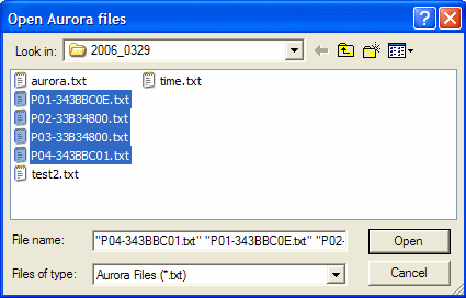
Select the four signals (as stored in four separate files).
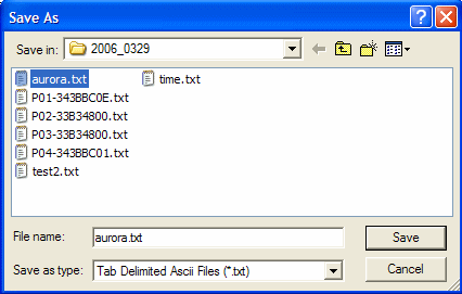
Select (or specify) the output file that will contain all four (in this case) signals.
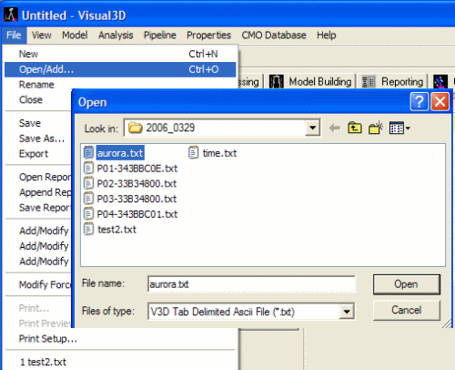
Open the text file that was just created. Select File → Open. Select the viewer for .txt files. Select “aurora.txt”.
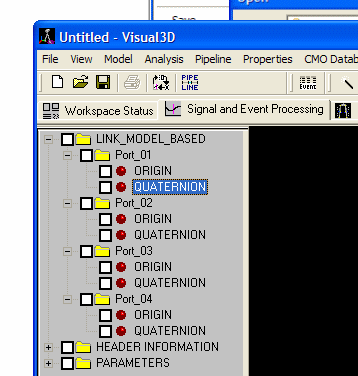
The file will be loaded into memory. The Aurora file contains position and rotation data for a rigid body. It will appear in Visual3D as LINKMODEL_BASED items containing the ORIGIN (3 components) and QUATERNION (4 components).
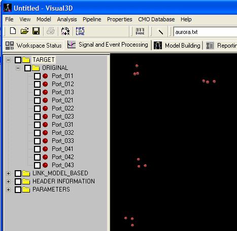
Visual3D typically works with motion capture markers, so to maximize your ability to work with this data, you can create a set of 3 targets per rigid body using the following command.
Create_Targets_For_LinkModelBased_Rotations
/SIGNAL_FOLDERS=Port_01+Port_02+Port_03+Port_04
;
Targets for each rigid body should appear in the data tree.
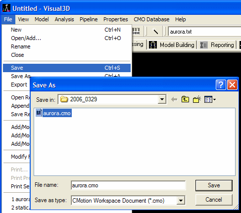
It is possible to save this data to a C3D formatted file, but the LINK MODEL data (e.g. the ORIGINAL Translation and Quaternion will be lost, so it is recommended that you save this data to a cmo file.
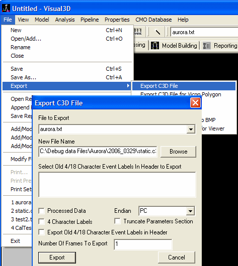
If you need a static trial for modeling the data, you can save the first frame of data to a c3d file.

