This is an old revision of the document!
Table of Contents
Metric Cross Product
Overview
The Metric Cross Product command is used to create a cross product of two metric vectors. This could include finding the torque acting on a joint or other similar uses. The command can be found within the Pipeline Workshop in the Metric folder. The command acts on the active files.
Pipeline Command
The command, as seen in the pipeline workshop, is below.
Metric_Cross_Product
! /RESULT_FILE=
! /RESULT_METRIC_FOLDER=PROCESSED
/RESULT_METRIC_NAME=
! /METRIC1_FILE=
! /METRIC1_FOLDER=PROCESSED
/METRIC1_NAME=
! /METRIC2_FILE=
! /METRIC2_FOLDER=PROCESSED
/METRIC2_NAME=
! /DIVIDE_BY_METRIC2_LENGTH=TRUE
! /GENERATE_MEAN_AND_STDDEV=TRUE
! /APPEND_TO_EXISTING_VALUES=FALSE
! /GENERATE_VECTOR_LENGTH_METRIC=FALSE
! /RETAIN_NO_DATA_VALUES=FALSE
;
Command Parameters
The following table shows the command parameters seen above and their descriptions:
| RESULT_METRIC_NAME | The name of the result signal |
| RESULT_METRIC_FOLDER | The name of the result signal folder |
| METRIC1_FILE | The movement trial containing the first metric value |
| METRIC1_NAME | The name of the signal containing the first metric value |
| METRIC1_FOLDER | The name of the metric signal folder |
| DIVIDE_BY_METRIC2_LENGTH | (True or False) Divide the resulting signal by the length of the second metric |
| GENERATE_MEAN_AND_STDDEV | (True or False)Generate the mean and standard deviation for all of the metrics created |
| APPEND_TO_EXISTING_VALUES | (True or False)Append this list of metrics to an existing metric of the same result name |
| GENERATE_VECTOR_LENGTH_METRIC | (True or False)Generate metric value for vector length |
| RETAIN_NO_DATA_VALUES | In cases where there is NO_DATA at an event, you need to specify the parameter /Retain_No_Data_Values=TRUE should you want this included in the resulting signal. |
Dialog
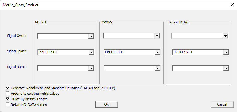
The command can be edited in a text editor or in a dialog form. To edit in the dialog pop up form either click on the Edit button in the pipeline workshop or double-click on the pipeline command. The dialog is shown below.
The dialog box allows you to assign values to the command parameters outlined above.
Metric_File
If Metric1_File or Metric2_File are empty, Visual3D uses each active file when processing the command.
These parameters exist because the user may want to compute the dot product relative to a signal in the GLOBAL workspace or a specified file.
Divide_By_Metric2_Length
When this is true, a unit vector of Metric2 is used.
Append_to_Existing_Values
The results are concatenated to an existing signal.
Example: Computing Step Length from Stride Vectors Using Dot Product
In this example the Metric Cross Product command is used along with Metric Vector Between Events and Automatic Gait Events to find the width of each step in a gait trial.
First all files are selected as active and key gait events are defined for each trial:
Select_Active_File
/FILE_NAME=ALL_FILES
;

Automatic_Gait_Events
! /FRAME_WINDOW=8
! /USE_TPR=TRUE
! /TPR_EVENT_INSTANCE=1
;
Next Metric Vector Between Events is used twice for each side to define vectors for the proximal end of each foot between gait events:
Metric_Vector_Between_Events
/START_SIGNAL_TYPE=KINETIC_KINEMATIC
/START_SIGNAL_NAME=ProxEndPos
/START_SIGNAL_FOLDER=LFT
/END_SIGNAL_TYPE=KINETIC_KINEMATIC
/END_SIGNAL_NAME=ProxEndPos
/END_SIGNAL_FOLDER=LFT
/EVENT_SEQUENCE=LHS+LHS
/EXCLUDE_EVENTS=
/METRIC_NAME=StrideVectors
! /GENERATE_MEAN_AND_STDDEV=TRUE
! /APPEND_TO_EXISTING_VALUES=FALSE
! /GENERATE_VECTOR_LENGTH_METRIC=FALSE
;

Metric_Vector_Between_Events
/START_SIGNAL_TYPE=KINETIC_KINEMATIC
/START_SIGNAL_NAME=ProxEndPos
/START_SIGNAL_FOLDER=RFT
/END_SIGNAL_TYPE=KINETIC_KINEMATIC
/END_SIGNAL_NAME=ProxEndPos
/END_SIGNAL_FOLDER=RFT
/EVENT_SEQUENCE=RHS+RHS
/EXCLUDE_EVENTS=
/METRIC_NAME=StrideVectors
! /GENERATE_MEAN_AND_STDDEV=TRUE
/APPEND_TO_EXISTING_VALUES=TRUE
! /GENERATE_VECTOR_LENGTH_METRIC=FALSE
;

Metric_Vector_Between_Events
/START_SIGNAL_TYPE=KINETIC_KINEMATIC
/START_SIGNAL_NAME=ProxEndPos
/START_SIGNAL_FOLDER=RFT
/END_SIGNAL_TYPE=KINETIC_KINEMATIC
/END_SIGNAL_NAME=ProxEndPos
/END_SIGNAL_FOLDER=LFT
/EVENT_SEQUENCE=RHS+LHS
/EXCLUDE_EVENTS=
/METRIC_NAME=LeftStep
/GENERATE_MEAN_AND_STDDEV=FALSE
! /APPEND_TO_EXISTING_VALUES=FALSE
! /GENERATE_VECTOR_LENGTH_METRIC=FALSE
;

Metric_Vector_Between_Events
/START_SIGNAL_TYPE=KINETIC_KINEMATIC
/START_SIGNAL_NAME=ProxEndPos
/START_SIGNAL_FOLDER=LFT
/END_SIGNAL_TYPE=KINETIC_KINEMATIC
/END_SIGNAL_NAME=ProxEndPos
/END_SIGNAL_FOLDER=RFT
/EVENT_SEQUENCE=LHS+RHS
/EXCLUDE_EVENTS=
/METRIC_NAME=RightStep
/GENERATE_MEAN_AND_STDDEV=FALSE
! /APPEND_TO_EXISTING_VALUES=FALSE
! /GENERATE_VECTOR_LENGTH_METRIC=FALSE
;
Now that the vectors for the feet have been defined, Metric Cross Product can be used to compute the dot product of those vectors and determine the step width for each stride:
! Calculate LeftStepWidth by taking cross product of LeftStep vector and StrideVectors_MEAN
! Generate Mean and STD DEV
Metric_Cross_Product
! /METRIC1_FILE=
/METRIC1_NAME=LeftStep
! /METRIC1_FOLDER=PROCESSED
/METRIC2_FILE=GLOBAL
/METRIC2_NAME=StrideVectors_MEAN
! /METRIC2_FOLDER=PROCESSED
! /DIVIDE_BY_METRIC2_LENGTH=TRUE
/RESULT_METRIC_NAME=LeftStepWidth
! /RESULT_METRIC_FOLDER=PROCESSED
! /GENERATE_MEAN_AND_STDDEV=TRUE
! /APPEND_TO_EXISTING_VALUES=FALSE
/GENERATE_VECTOR_LENGTH_METRIC=TRUE
;

! Calculate RightStepWidth by taking cross product of RightStep vector and StrideVectors_MEAN
! Generate Mean and STD DEV
Metric_Cross_Product
! /METRIC1_FILE=
/METRIC1_NAME=RightStep
! /METRIC1_FOLDER=PROCESSED
/METRIC2_FILE=GLOBAL
/METRIC2_NAME=StrideVectors_MEAN
! /METRIC2_FOLDER=PROCESSED
! /DIVIDE_BY_METRIC2_LENGTH=TRUE
/RESULT_METRIC_NAME=RightStepWidth
! /RESULT_METRIC_FOLDER=PROCESSED
! /GENERATE_MEAN_AND_STDDEV=TRUE
! /APPEND_TO_EXISTING_VALUES=FALSE
/GENERATE_VECTOR_LENGTH_METRIC=TRUE
;
The METRIC:PROCESSED folder should now contain several new metrics including 3= values (vector, mean, and std dev) for right and left step width. The results should look similar to below:
A more complete example including dot products is available here.


