Table of Contents
MODEL MOMENT OF INERTIA
For more information on Moment of Inertia see here]
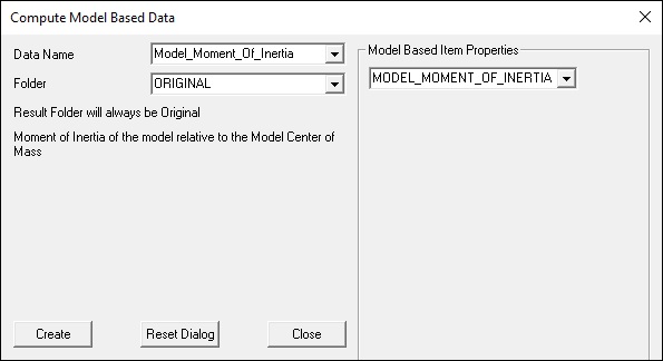
Moment of Inertia Command
The result is the model's moment of inertia around the model's center of mass. This result is the sum of each segment's moment of inertia around the model's center of mass. So the equations apply to each segment, and the total body moment of inertia is the sum of these values.
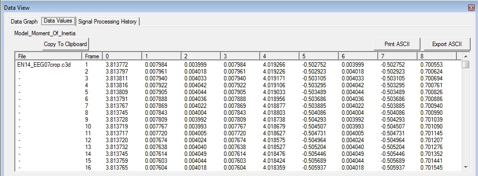
Moment of Inertia Signal
The Model_Momentum_Inertia is a 3×3 matrix. The data at each frame represents the 9 values in this matrix.
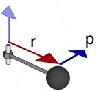
Moment of Inertia of a Particle
Moment of Inertia of a Segment
Give a segment with mass m and local moment of inertia I.
The moment of inertia of any object about an axis through its center of mass is the minimum moment of inertia for an axis in that direction in space.
The moment of inertia about any axis parallel to that axis through the center of mass is given by:
 Thus the moment of inertia of the body (relative to global coordinate system) is given by summing two terms:
 A parallel axis theorem term which accounts for the distance each body is from the point you are calculated the center of mass about. (Often this point is the total body center of mass).
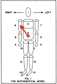
Model Center of Mass (COM)
The center of mass of an object is a theoretical point where all of the object’s mass can be considered to be concentrated
Compute the Center of Mass of the model from the location of the center of mass of each segment.

Moment of inertia is the name given to rotational inertia, the rotational analog of mass for linear motion.
The moment of inertia must be specified with respect to a chosen axis of rotation.
For a point mass the moment of inertia is just the mass times the square of perpendicular distance to the rotation axis, I = mr2.
The moment of inertia of a body is not only related to its mass but also the distribution of the mass throughout the body. So two bodies of the same mass may possess different moments of inertia
Moment of Inertia of a Segment in Laboratory Coordinates
Parallel Axis
 Now the tricky bit (proved in the next section). The Principal Moment of Inertia in Laboratory Coordinates is.
 where R = Segment orientation matrix, which transforms a vector from Lab coordinates to Local coordinates
Moment of Inertia of a Model in Laboratory Coordinates
If the moment of inertia of each segment is resolved about the center of mass of the model in the laboratory coordinates, the moment of inertia of the model is simply the sum of the moment of inertia of the segments about the center of mass of the model.
Note that the key concept is that the segment moments of inertia must be expressed in Laboratory coordinates.

Proof Courtesy of Fred Yeadon
One of the tricky bits is recognizing the following equation.
 Fred Yeadon provided us with a straightforward proof.
Let:
 = the angular velocity vector in the segment frame s
 = the angular momentum vector in coordinate system s
 = matrix that transforms a vector from frame s to frame f
Thus:


What we are trying to demonstrate is

If the tensor  transforms into
  and
if the vector
  transforms into
  then:-

 because
  if the associative rule is to hold
 Therefore, as expected:

Much of the contents of this page are courtesy of Fred Yeadon.
Yeadon, M.R. 1993. The biomechanics of twisting somersaults. Part I: Rigid body motions. Journal of Sports Sciences 11, 187-198.
Yeadon, M.R. 1993. The biomechanics of twisting somersaults. Part II: Contact twist. Journal of Sports Sciences 11, 199-208.
Yeadon, M.R. 1993. The biomechanics of twisting somersaults. Part III: Aerial twist. Journal of Sports Sciences 11, 209-218.
Yeadon, M.R. 1993. The biomechanics of twisting somersaults. Part IV: Partitioning performance using the tilt angle. Journal of Sports Sciences 11, 219-225.
Yeadon, M.R. 1993. Twisting techniques used by competitive divers. Journal of Sports Sciences 11, 4, 337-342.


