Table of Contents
Compute Distance Map
Compute Distance Map
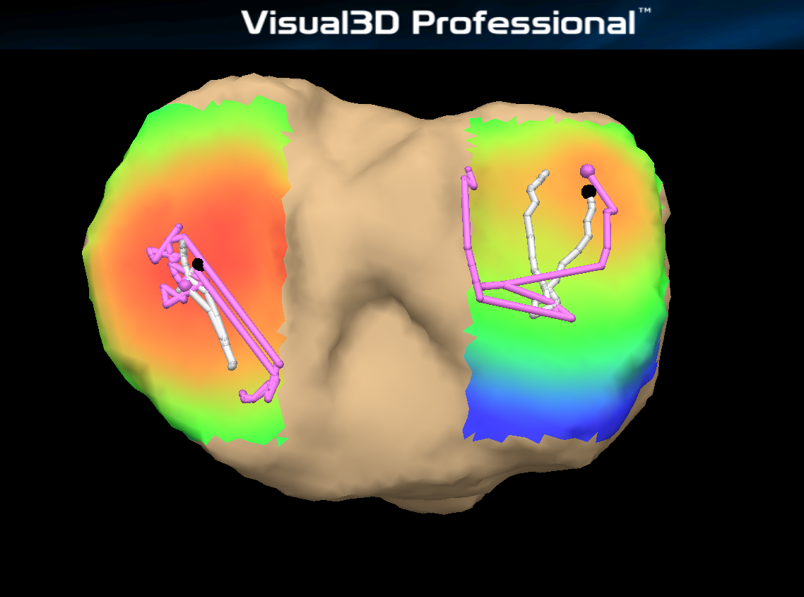
This command will color two regions of interest (ROI) on opposing segments, and calculate the weighted-average contact point on each one. The ROIs are defined in OBJ files created with DSX.
Distance maps:
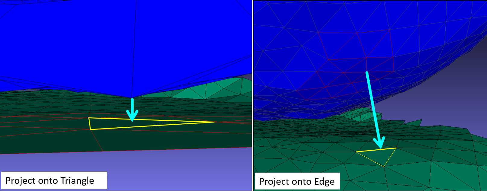
- Each vertex is colored according to its closest distance to the other surface (which can be to a vertex, edge, or triangle of the other surface). Smooth shading is used so that a triangle's color is a linear combination of the colors of its three vertices.
Contact point:
- The overall minimum distance is calculated (_Min)
- The contact point is the weighted minimum distance (_Contact)
Background
A polygonal surface mesh is defined by a set of faces, each of which is defined by a set of vertices connected by edges. Before computing distances, the Compute Distance Map command divides all faces of the ROIs into triangles, for easier processing and to guarantee that all faces are planar. In the image below, the left image highlights the vertices used to define a surface and the right image displays the triangles that define the surface:
A normal vector is defined for each triangle, vertex and edge:
Command Output
| For every Result Name specified, there will be 6 results: * ResultName_SegmentName_Min * ResultName_SegmentName_Contact * ResultName_SegmentName_Vert | 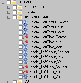 |
The result for _Min and _Contact will have 4 components. The first three components are X Y Z location of the contact point in the segment coordinate system, and the fourth component is the minimum distance. You can use the Transform_Data_Coordinate_System command to transform the resulting coordinate system of the contact point.
Minimum Distance
Contact Point
The weighted minimum distance between the two segments.
- Once each triangle has been assigned a minimum distance, a preliminary contact point is found by calculating a weighted average of all the triangle centers. Each center is weighted by the triangle's area and the square of its distance. The area threshold percentage (CONTACT_POINT_AREA_THRESHOLD) specifies the percentage of the total area of triangles on the ROI to be included in the calculation. This weighted-average point is usually not on the surface of the ROI, so it is projected onto the surface using the normal of the closest ROI vertex.
Min Vertex Distances
This is the minimum distance value that is used to color each vertex in the OBJ.
Note: Do not click on this signal and open the data view, Visual3D will not be able to open the data view due to the number of columns.
Sign of the Minimum Distance
Any of the distances calculated by this command can be positive (the opposing ROI surfaces do not intersect) or negative (the surfaces intersect). The sign of each distance is calculated using the appropriate normal vector (triangle, edge, or vertex). For example, to determine which side of a triangle a given vertex is on, the vector from the vertex to the triangle is compared to the normal of the triangle.
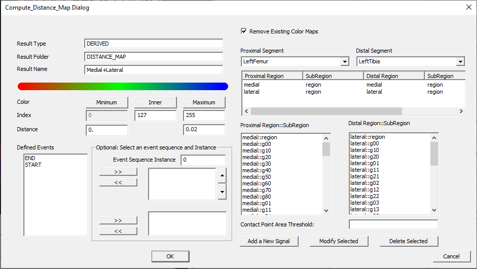
Command Dialog
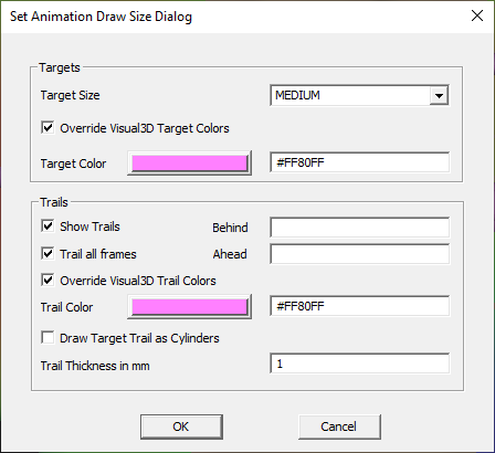
Drawing the Contact Path
Steps
| For every Result Name specified, there will be 6 results: * ResultName_SegmentName_Contact * ResultName_SegmentName_Min * ResultName_SegmentName_Vert Right click on the _Min or _Contact to specify the draw properties | 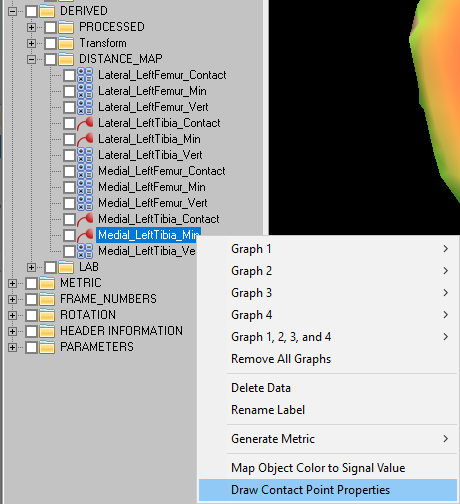 |
NOTE: If the contact point is still too large, go to Settings → Modify Scale of 3D Graphics and decrease the Target Size.
Camera Settings
The skeleton toggle button on the toolbar turns segment drawings on/off:
- All on
- Kinematic on
- Kinetic on
- All off
You can set one segment to be always drawn by right click on the segment name under Kinetic_Kinematic in the data tree, and selecting “Draw Segment Properties”. Check “Draw Segment (Override Visual3D Global Draw)”, this means the segment will always be drawn.
You can manually adjust the camera perspective:
- Right Mouse: Zoom in/out
- Left Mouse: Rotation
- Right + Left Mouse: Translate
You can set the camera perspective to lock onto a segment by going to View → Set Camera Perspective.


