Computing Custom Digitizing Pointer Configuration
Users can construct their own digitizing pointer. The following steps demonstrate how to compute the location of the pointer tip relative to the markers attached to the rod.
This is especially useful for users that want to construct a pointer using an electromagnetic or inertial sensor, because it isn't obvious how to measure physically the location of the tip from the electromagnetic sensor housing.
The following file was collected by streaming data from a Polhemus Liberty system into Visual3D.
https://www.has-motion.com/download/examples/LlibertyDigitizingPointer.c3d
Step1. Open the file in Visual3D
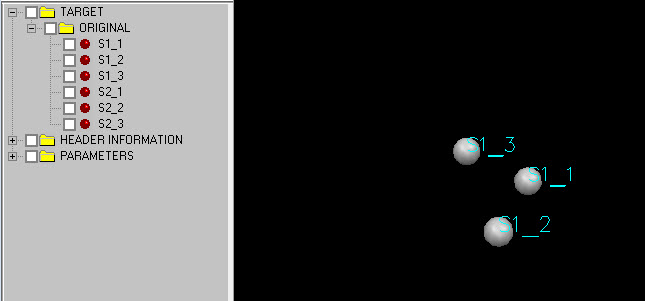
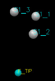
Note that Visual3D displays the 6 degree of freedom information from the Liberty sensor as 3 TARGETS. This file contains two Liberty sensors, which translates to 6 targets (3 for each sensor).
Sensor 1 is attached to a pointer, so the movement of the pointer is defined by markers S1_1, S1_2, S1_3.
In this file the pointer tip has been placed on the ground, and keeping the tip in contact with the ground, the pointer is rotated about that point.
The location of the tip is a stationary point, which means that we can compute its location as a functional joint.
Step 2. Create a hybrid model using the same movement trial
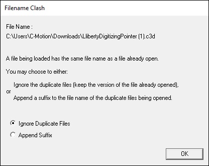
A dialog will appear indicating that the file is already open in the workspace. Select the option to add a suffix to the filename.
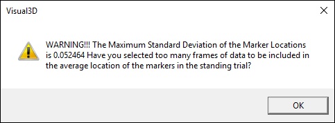
Another dialog will appear stating that the markers are not stationary.
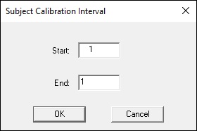
Remember that we have loaded a movement trial, so in order for the average location of the markers to have any meaning, we must select only 1 frame of this trial.
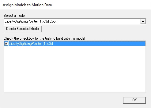
Step 3. Assign the movement trial to the model file
Step 4. Assign the frames for the static trial
under the model menu select the option to “modify frame range for static calibration” and specify only one frame of data.
A warning will appear saying that the model has no Mass and default value of 1 will be used. This default value is fine because we are not computing kinetics from this data.
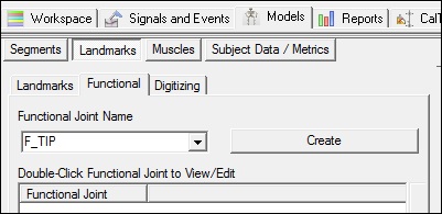
Step 5. Create a functional joint definition for the tip (F_TIP)
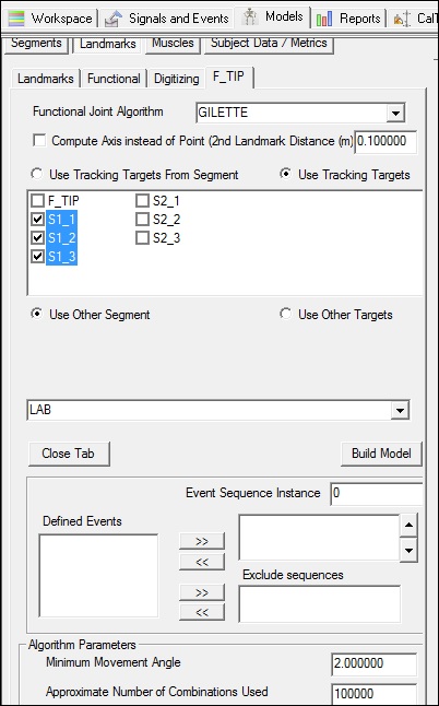
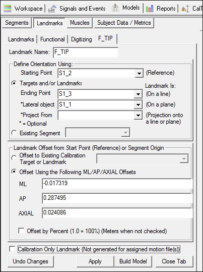
Note that there isn't a default definition for this landmark, so you should type F_TIP into the combo box as shown.
Select the Create button.
Enter the information above. The landmark will be created relative to the 3 targets (eg. liberty sensor 1) and the movement will be computed relative to the LAB.
Step 6. Compute the functional joint
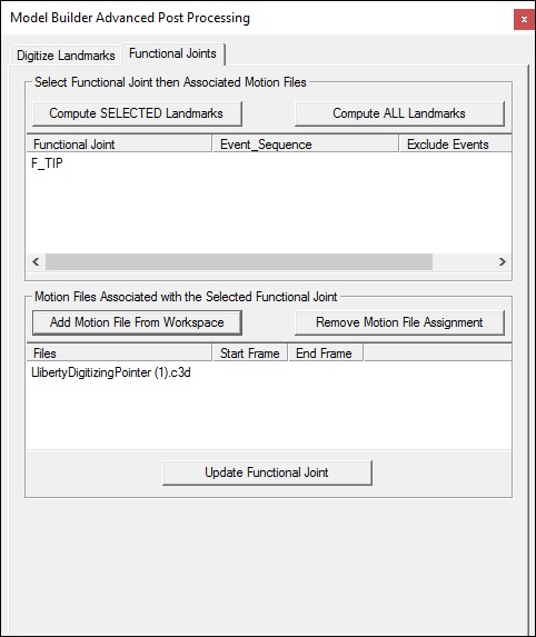
Select the Model Builder PostProcessing item on the Toolbar.
Switch to the Functional Joints tab and select the button “add motion files from Workspace”.
Select the motion file. At this point you should be able to animate the motion file.
Specify the range of frames to be used for the functional joint calculation by selecting the buttons “Set START Event to Current Frame” and “Set END Event to Current Frame”. Current Frame refers to the frame of data shown in the animation viewer.
Select “Compute SELECTED Landmarks”
A landmark should appear in the animation viewer, and an instance of the functional joint should appear as a Landmark
edit the landmark. Note that the location of the tip is relative to the 3 markers.
Visual3D has selected the order of the 3 markers automatically based on a set of internal rules. There is no need to modify the default selection.
Step 7. Specify the pointer configuration
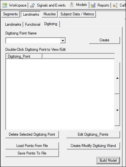
Switch to the Digitizing Landmarks Tab
Select the button “Create/Modify Digitizing Wand”
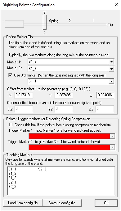
Populate the dialog as shown.
The order of the markers and the offsets are extracted from F_TIP landmark definition above.
Note especially that the offset locations are the negative of the F_TIP landmark locations. This is because Visual3D has a subtly different mechanism for specifying landmarks relative to markers, and landmarks relative to segments. The digitizing pointer is treated as a segment.
Select the option “Save to config file”.
This config file can then be loaded for subsequent trials.

