Computing the Dimensions of the CalTester Rod
The dimensions of the CalTester Rod can be computed from Motion Data using the Functional Joints Landmarks.

Select the CalTester Dimensions Icon from the Toolbar
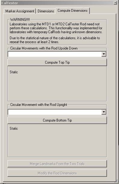
You will need to collect 2 movement trials in which the tip of the CalTester rod is secured into the plate divot for the entire trial. The movement is similar to the typical test movement of the CalTester Rod. One of the trials will have the top of the rod in the divot (e.g. down) and the other trial will have the bottom of the rod in the divot (e.g. down).
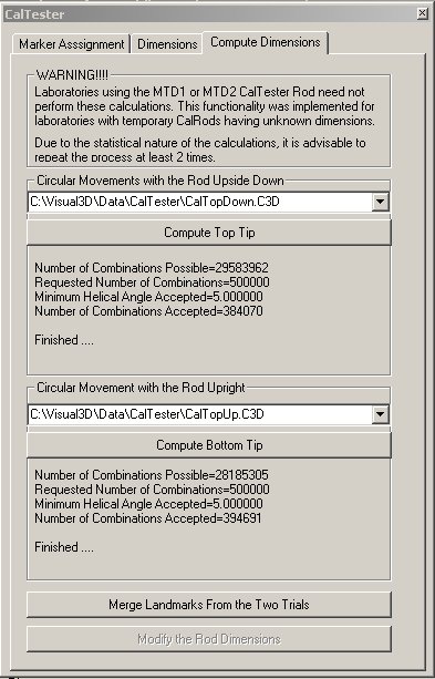
Switch to CalTester mode and open the two files (e.g. CalTopDown.c3d and CalTopUp.c3d)
Select the buttons for Compute Top Tip and Compute Bottom Tip
Select Merge Landmarks From the Two Trials
Select Modify the Rod Dimensions
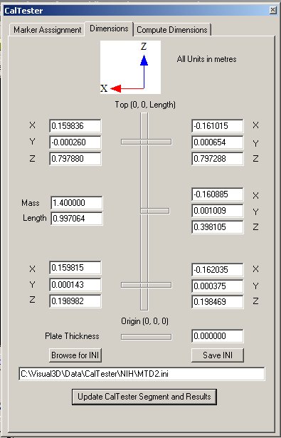
if you switch to the Dimensions Tab, you will see the updated results
Note that this test was done using the MTD2 rod. Notice that the dimensions are not identical with the Default Dimensions because of limitations in the motion capture system and in the functional joints calculation.


