3DViewerAnimationControls
3D Viewer Animation Controls
The viewer is a 3D display (using the OpenGL libraries) of your marker set as seen from multiple camera angles.
Left Mouse Button (Pan)
The left mouse button is used to modify the orientation of the 3D model. Holding down the left mouse button and moving the mouse up and down rotates the model up and down, moving the mouse from side to side rotates the model from side to side.
Right Mouse Button (Zoom)
The right mouse button is used to modify the scaling of the model. Holding down the right mouse button and moving the mouse up or right moves the camera closer to the center of the model (increases the size of the image displayed). Holding down the right mouse button and moving the mouse down or left moves the camera further from the center of the model (decreases the size of the image displayed).
Center Mouse Button (Move)
Holding down the center mouse button (or both the left and right mouse buttons together on a 2-button mouse), allows the user to shift (translate) the model from side to side and up or down.
Note: You will notice that once you move the model a white cross-hair is temporarily added to the scene. This is provided to assist you with centering your model in the scene.
Modify the Viewer Settings
What you see in the 3D viewer varies with the viewing options you select.
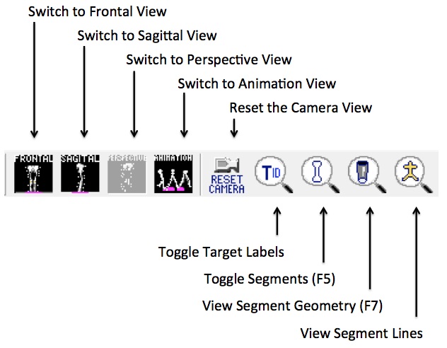
Frontal View:
Sets the camera's perspective to view the front of the model from the anterior direction as defined by the lab's anterior/posterior axis.
Sagittal View:
Sets the camera's perspective to view the side of the model from the alter direction as defined by the lab's medial/lateral axis.
Perspective View:
Allows you to view the model from any angle. This is the default view when the 3D Viewer is first opened. This view allows you to choose the camera's perspective by dragging the mouse around the scene.
Reset Camera Perspective:
Sets the camera to look at the lab origin. If you have gotten “lost” in the scene, you can use this button to quickly get you back to a “known” point, the lab's origin.
Toggle Marker names:
Cycles through target labels, target labels with landmark labels, or no target labels.
View Segments:
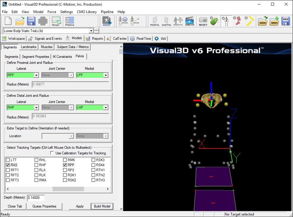
Clicking the View Segments toggle  button will toggle on and off the model files assigned to the segments. The model files are wire frame objects formatted as either a .v3g or .obj file or a VRML .wrl file. The model file is usually a representation of the bone(s) used for the 3D animation. In the example the model file is a 3D representation of the pelvis bone.
Note: The 3D animation object is purely for visualization. You can rotate, scale or move the bones relative to the segment coordinate system and it will not affect the analysis.
View Segment Geometry:
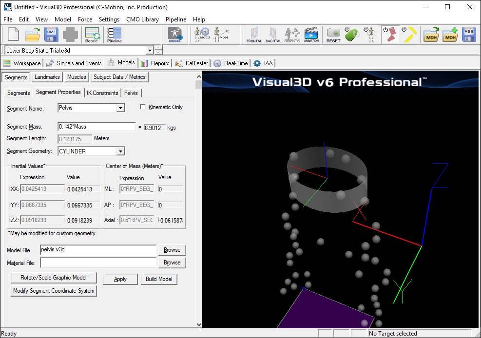
To view the geometry click the View Segment Geometry toggle button  on the toolbar.
- The width of the cylinder is defined by the endpoint radii of the segment.
- The depth of the cylinder is defined by the depth of the pelvis.
View Segment Lines:
View segment lines allows you to view a “stick figure” of the segment(s).
click the View Segment Lines  toggle button.
The yellow segment lines displayed are:
A vertical line between the segment endpoints
Two horizontal lines between the medial and lateral radii of the segment (e.g. from the segment endpoint to the medial and lateral borders of the segment, which are one radius away.)


