Table of Contents
Menus
Although many of the features in Visual3D can be accessed in multiple ways, the drop-down menus across the top of the Visual3D page offer a familiar method of program interaction that is common to Windows-based software.
This Visual3D Menus link provides details on the options available through these drop-down menus. Because we are constantly adding more features, the menus in Visual3D often change before this documentation can be updated. Please contact us if there are features on the menus that are not described here.
File Menu
New
Closes all open files, leaving an empty workspace.
Open
Opens a new motion document (C3D, CMZ, etc.)
Close
Closes the currently active motion file(s) as indicated by the active file selection box.
Save Workspace
Saves all open files to the current C-Motion (cmz) Document.
Save Workspace As
Prompts the user with the file save dialog in order to save all open files to a new or existing C-Motion (cmz) Document.
Export
Export C3D File
Exports an opened file to a C3D File (.c3d).
Export C3DFile for Vicon Polygon
Pipeline Command
Export Animation to AVI
Exports the 3D animation to an AVI (.avi) file.
Export Animation Frame to Image
Exports the current animation viewer frame to an Image (.jpg, .png, .gif, .bmp).
Export Standalone CMO for Viewer
CMO files do not typically contain the wireframe meshes used for animating the surfaces of the bones because this information is supplied with Visual3D (e.g. as .v3g files).
CMO files intended for the Free CMO viewer, however, must explicitly embed the graphics by selecting the export option to include the graphics.
Add Modify File Tags
Brings up a window to add/modify file tags
Add_Modify_Synchronized_Video_Files
Add_Modify_Synchronized_Video_Files
Allows mapping of video files (.mpg, .avi, etc) to motion files for synchronized playback.
Add Modify Synchronized Motion Files
Add_Modify_Synchronized_Motion_Files
Allows multiselection of C3D motion files and frame offsets for synchronized playback.
Modify Force Platform Parameters
Allows modification of the active file(s) force platform C3D file parameters
Prints the current report
Print Preview
Previews the current report.
Print Setup
Change the printer and printer options.
Exit
Exits the Visual 3D application.
Edit Menu
Program Options
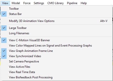
View Menu
Toolbar
Large Toolbar
Status Bar
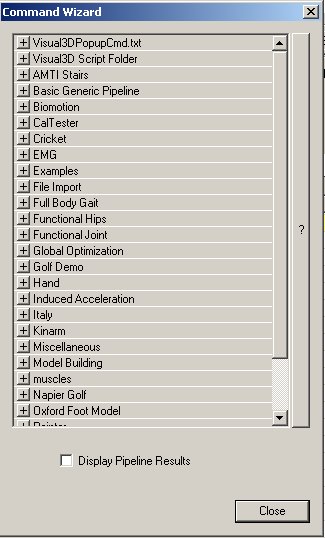
View Popup Wizard
Long Filenames
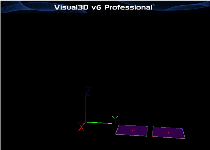
View HAS-Motion Visual3D Banner
View Color Mapped Lines on Signal and Event Processing Graphs
View Graph Animation Frame Line
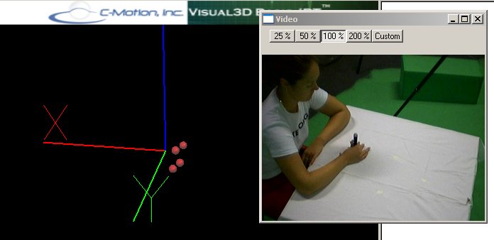
View Synchronized Video
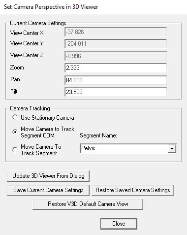
Set Camera Perspective
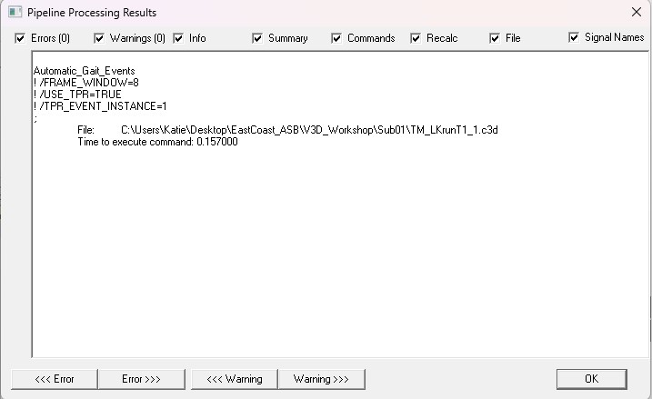
Processing Results
Model Menu
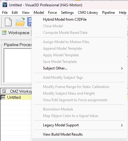
The model menu is dedicated to features related predominantly to a Link Model.
When no model is loaded in Visual3D only the option to create a model is available.
Create (Add Static Calibration File)
Creates a new model (Hybrid, 6DOF, Helen Hayes & Derived...) A static calibration file must be opened with the new model because there is a direct one-to-one link between the standing trial and the model.
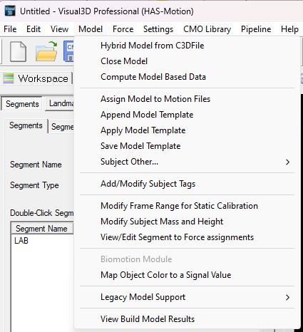
When a model is loaded the following features are available
Compute Model Based Data
Brings up a window to create or modify model based calculations (such as joint angles, joint powers, etc.) The resulting data is created on the files specified in the file selection combo.
Assign Model to Motion File
Allows the user to specify which model is to be applied to each movement trial.
Close Model
Closes the current model
Convert Model To Hybrid
Convert a Visual3D Legacy model to a Hybrid Model
Apply Model Template
Opens a model template file (.mdh, .mod, .bsp) to be applied to the currently active model. All existing segments, landmarks, etc. are deleted prior to applying the new template
Save Model Template
Saves the currently active model to a file (.mdh, .mod).
Append Model Template
to current model Adds the segment, landmarks, etc in the template to the current model without deleting the current attributes
Modify Subject Mass and Height
Modify the model properties. Note that these values are also subject metrics that can be edited in the Subject Data/Metrics property page
Modify Frame Range for Subject Cal
Modifies the frame range to use for the subject calibration file.
View/Edit Segment to Force assignments
Modify the segment assignments
Color Item with Signal Value
Allows the user to map signals to segments, and select color values to color a segment based upon the signal values.
Force
Minimum Force
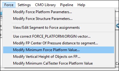
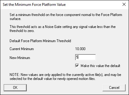
Visual3D's Force menu contains an option to set a threshold for force platform/structure data.
Applying a threshold value to the force signals ensures that If the computed force is less than the minimum force, then the FORCE and FREEMOMENT are set to zero, the COFP is set to DATA_NOT_FOUND. This value can also be set using the pipeline command Set_Force_Platform_Threshold. This command is listed under the Force category of the pipeline commands. This threshold value is used to remove noise from the force signals. Often for instrumented treadmills this value must be set higher than for overground gait trials.
Settings
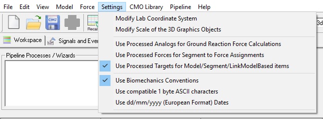
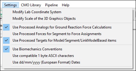
The Program Settings menu item is used to manage various properties of motion files and the Visual 3D environment.
Modify Lab Coordinate System
Changes the X, Y and Z directions for the lab.
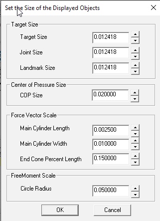
Modify Scale of the 3D Graphics Objects
Use Processed Analogs for Ground Reaction Force Calculations
Specify whether the original or processed analog signals should be used for computing the Ground Reaction Force
Use Processed Forces for Segment to Force Assignment
Specify that processed FORCE, COFP, and FREEMOMENT signals should be used for determining the Force Assignments.
Use Processed Targets for Model/Segment/LinkModelBased Items
Specify whether the original or processed targets are to be used for determining model segment locations, model based computations, etc.
Use Biomechanics Conventions
Biomechanics conventions refer to the meaning for medial/lateral, anterior/posterior, and axial for the left and right side segments.
Note that medial and lateral are defined with respect to the subject in the Anatomical Position, which is important to remember when defining the forearm and hand segments. If Biomechanics Conventions are not selected, all coordinate system use the right hand rule, and left and right side segments are created equivalently. The typical consequence is that the left side segments look like they are constructed backwards.
Use Compatible 1 Byte Characters
There are some unicode characters that Visual3D cannot recognize.


