This is an old revision of the document!
Table of Contents
Force Platforms
Overview
Force Platforms provide critical data for biomechanical analysis because they measure the interaction between the subject and the environment. If the subject is in contact with the floor, the joint forces, moments and powers have no physical meaning unless the reaction force data are included in the analysis.
Note: The Analog signals that are collected from the force platform are NOT the force signals. The force signals must be computed from these Analog signals using several parameters that specify the type of computations required (different force platforms require different computations).
C3D Parameters
The following parameters should exist:
FP_USED = number of force platforms used
FP_TYPE = 4
FP_ZERO = the range of frames for which a background noise level is calculated and then subtracted from each of the analog channels
FP_CHANNELS = Fx, Fy, Fz, Mx, My, Mz
FP_ORIGIN = The origin of the force platform in the force platform coordinate system (see the force platform manufacturer specifications.
FP_CORNERS = The (x,y,z) coordinates of the force platform corners in the laboratory coordinate system. Note that there is a specific ordering of the four corners.
FP_CALMATRIX = 6 x 6 Calibration Matrix.
Compute Force, COP, and FreeMoment

This figure depicts a Kistler force platform, but the diagrammed force vector is consistent with all force platforms.
C3D Channels
The number of channels associated with a force platform varies with the force platform manufacturer (usually represented as a force platform TYPE in the c3d format).
For example (other options exist),
Type 2, Type 3, and Type 4 platforms have 6 channels as follows as specified by the ANALOG channel numbers:
- [Original Analog]= [Fx_original, Fy_original, Fz_original, Mx_original, My_original, Mz_original]
Type 3 and Type 7 platforms have 8 channels as follows as specified by the ANALOG channel numbers:
- [Original Analog]= [Fx12, Fx34, Fy14, Fy23, Fz1, Fz2, Fz3, Fz4]
Type 3 and Type 6 platforms have 8 channels as follows as specified by the ANALOG channel numbers:
- [Original Analog]= [Fx1, Fy1, Fz1, Fx2, Fy2, Fz2, Fx3, Fy3, Fz3, Fx4, Fy4, Fz4]
Compute Baselines
The FORCE_PLATFORM:ZERO C3D parameter defines the range of frames used to calculate an average baseline value for each ANALOG signal that is then subtracted from every frame. This does not affect the ANALOG signals (as seen in the data tree), this processing takes place when the Force Platform signals are computed.
Note that most of the manufacturers arbitrarily set the range to be the first 10 frames of the trial. If the force platform is loaded during these first 10 frames, the ground reaction force signals will be incorrect; in this case the user should either set the frames to 0,0 so that no baseline is subtracted, or should select frames in which the force platform is unloaded.
Subtract Baselines
[Tared Analog]= [Original Analog]-[Baseline]
Pre-Multiply by the CalMatrix
Several of the force platform types have a Calibration Matrix (Inverse Sensitivity Matrix) that is provided by the manufacturer. Pre-multiplying (by Visual3D) of the analog channels by this calibration matrix converts the signals from volts to the appropriate Force and/or Moment signal units.
For example:
For a type 4
[Analog]= [Fx, Fy, Fz, Mx, My, Mz]= [CalMatrix][Original Analog]
For a type 7
[Analog]= [Fx12, Fx34, Fy14, Fy23, Fz1, Fz2, Fz3, Fz4]= [CalMatrix][Original Analog]
These signals are intermediate signals that are then used to compute the Ground Reaction Force
The Ground Reaction Force
The Ground Reaction Force is represented by 3 vectors.
- Force
- Center of Pressure
- Free Moment
Force Vector
Different force platform types have different calculations for the force vector.
In the simplest case (Types 2 & 4), the force vector is equal to the intermediate force signals from the previous step.
Force[X] = Fx
Force[Y] = Fy
Force[Z] = Fz
Center of Pressure Vector
Different force platform types have different calculations for the center of pressure vector.
For Types 2 & 4, the center of pressure vector is computed as follows:
COP[X] = (ORIGIN[Z]*Force[X] - My) / Force[Z]
COP[Y] = (Mx + ORIGIN[Z]*Force[Y]) / Force[Z]
COP[Z] = ORIGIN[Z}
Note the use of an ORIGIN vector.
Free Moment Vector
Different force platform types have different calculations for the center of pressure vector.
For Types 2 & 4, the free moment vector is computed as follows:
FreeMoment[X] = 0
FreeMoment[Y] = 0
FreeMoment[Z] = Mz - ( COP[X]*Force[Y] - COP[Y]*Force[X] )
Applying Threshold
Under the Visual3D Force Menu is an option to set a threshold for force platform/structure data.
Any signal value less than this threshold is set to 0 (is assumed to be noise).
Transforming data to the Laboratory Coordinate System
At this point the signals have been computed in the Force Platform Coordinate system and must be transformed into the Laboratory Coordinate System to give them meaning relative to the Motion Capture Data.
Translate from Force platform Coordinate System (FCS) to Lab Coordinate System(LCS)
Example
The following example creates the force platform parameters for a c3d file that contains the ANALOG signals from the force platform but does not contain any parameters.
- Select Modify Force Platform Parameters from under the File Menu. The following dialog will appear
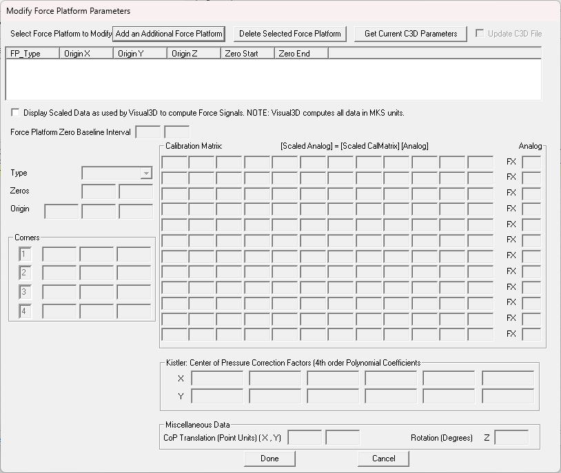
- Select the Get Current C3D Parameters. There should be no change to the dialog because there aren't any parameters in the file. You can check this by looking in the Parameters section of the Data Tree; there should be only one parameter used, which is equal to zero indicating no force platforms.

- For a type 4 force platform the edit boxes shown must be filled in.
- The CalMatrix and ORIGIN parameters are provided in the AMTI manual. Each force platform has different values.
- The channel numbers should correspond with the force platform signals. Visual3D stores the ANALOG signals alphabetically in the data tree, which is not necessarily consistent with the C3D file order. To see the C3D order you must look in the ANALOG parameters.
- The force platform corners are the locations of the corners of the force platform in the laboratory coordinate system.
- Download a pipeline command to modify the force platform parameters for the example file.
- From the Visual3D pipeline, load the pipeline file that you just downloaded. Execute the pipeline and all force platform parameters will be updated.


Modifying the Force Platform Parameters
Force Platform data are perhaps the most confusing aspects of the C3D file format. All of the required Force Platform parameters for the type of Force Platform must be defined correctly. Some of the parameters are specified by the Force Platform manufacturer; these values are provided in the Manufacturers User Manual. Note that some of these parameters can not be transferred directly in the C3D file.
Important: The C3D format assumes consistency between units throughout the file. If the Motion Capture data has been collected in millimeters, ALL distance measures in the file must be consistent. This means that the corner locations, and Force Platform ORIGIN values must be in millimeters, and the moment channels of the force platform must be expressed in Newton-millimeters.
To examine or modify the parameters.
- In the Force menu, select Modify Force Platform Parameters.

- Click the Get Current C3D Parameters button to populate the dialog box.
The Force Platform Zero Baseline Interval indicates that the first 10 frames of data will be averaged to define a baseline, which is then subtracted from every frame of data.
The ORIGIN (mm) shows a –21 mm Z component. The manufacturer manual will show a positive z-component. The c3d format assumes that this value will be a vector from the ORIGIN to the center of the top surface of the platform in the force platform coordinate system, which means that the value in the C3D file should be negative.
Corner 1, Corner 2, Corner 3 and Corner 4 are the locations of the force platform corners specified in the laboratory coordinate system. This information is used to transform the signals from the force platform coordinate system to the laboratory coordinate system. In principle the force platform can be located in any orientation in the 3D data collection volume; e.g. the force platform does not have to be on the floor.
The Analog Channels column shows the analog channel assignment number in the order the ANALOG channels appear in the c3d file.
- Click Done or Cancel when finished examining data.

Thresholding the Force Platform Signals
When force platform data exists, Visual3D attempts to assign the signal to a segment that comes into contact with it. If there is a low level of background noise in the signal, it will appear that something must be in contact with the force platform at all times. To ensure that only “sensible/real” contacts are used, a threshold values is specified such that any ground reaction force signal below this value is assumed to be zero. This ensures clean contacts with the force platform.
- Select the Force menu.
- Click on the Modify Minimum Force Platform Value. A dialog box will open to allow you to set a higher (or lower) threshold than the default.

- You can also choose one of the other options for modifying force platforms. Select Modify FP Center of Pressure Distance to Segment to specify a minimum distance (.2m default). This option allows you to verify that a particular signal has been caused by a segment.

Graphing a Force Platform Signal
- If the graph area at the right is still occupied, right-click anywhere on the graph area and select Remove all graphs.
- In the Data Tree, open the folder labeled ANALOG, then the folder labeled ORIGINAL.
- Right-click FZ1, select Graph Signal, and New Graph. This will open a graph of the Fz ANALOG channel of force platform1.
- In the Data Tree, open the folder labeled FORCE then open the folder labeled ORGINAL.
- Right click FP1 and select Graph Z, and New Graph. This will open a graph of Z-component of the Ground Reaction Force signal.
Note: These two signals are related to each other, but they are not identical. The ANALOG signal is stored in the coordinate system of the force platform. The FORCE (ground force) signal is stored in the Laboratory (Motion Capture) Coordinate System.

Troubleshooting Tip: If the ANALOG signals for the force platform exist, but the FORCE signal is zero, examine the FZ1 graph and verify that the Fz Channel of the ANALOG signals is negative. If not, then the ANALOG scale factor in the C3D file has probably been stored incorrectly by the motion capture software. The scale factor will need to be changed in the motion capture software and/or the file.