Table of Contents
Model Based Computations
Objectives
The objective of this tutorial is to present Model Based Calculations. These are calculations that only make sense relative to rigid segments.
If you have a Ph.D. in Kinesiology or Biomechanics, or you are an M.D. or researcher – do not skim lightly or jump completely over these sections. This tutorial is written without as much jargon as possible to address a very broad customer base. However, the interfaces and techniques described are the exactly the same approaches and techniques used for the most sophisticated analyses.
Part of the power of Visual3D is the ability to determine exactly what and how calculations are done – and the ability to point to the published works proving its validity. From a pure tool perspective, the power is in additional Pipeline command parameters and options.
If you would like to follow along with a Youtube video tutorial based on this tutorial, please select the link here: Visual3D Tutorial Video 7: Model Based Computations
Analysis Goal
Some of the analysis characteristics we will examine will be positions of the pelvis and foot during gait, knee flexion and extension, and knee joint moments and powers. To do this we will define segment angles, joint angles, joint moments, and joint powers. We will also be reporting on basic attributes such as stride length and other fundamental gait characteristics.
- Create a report with basic gait information.
- Calculate joint angles to measure left and right knee flexion/extension.
- Add the computed signals to a report.
Preparation
- Download the following ZIP File: Visual3D Tutorial 7 Sample Data. It contains:
- Tutorial7_MBC_Start.cmz: Starting point of tutorial, CMZ file containing Lower Body Static Trial.c3d as the static/calibration file and Walking Trial 1.c3d as the motion file.
- Tutorial7_MBC_End.cmz: Final result of tutorial containing the model based computation definitions added throughout.
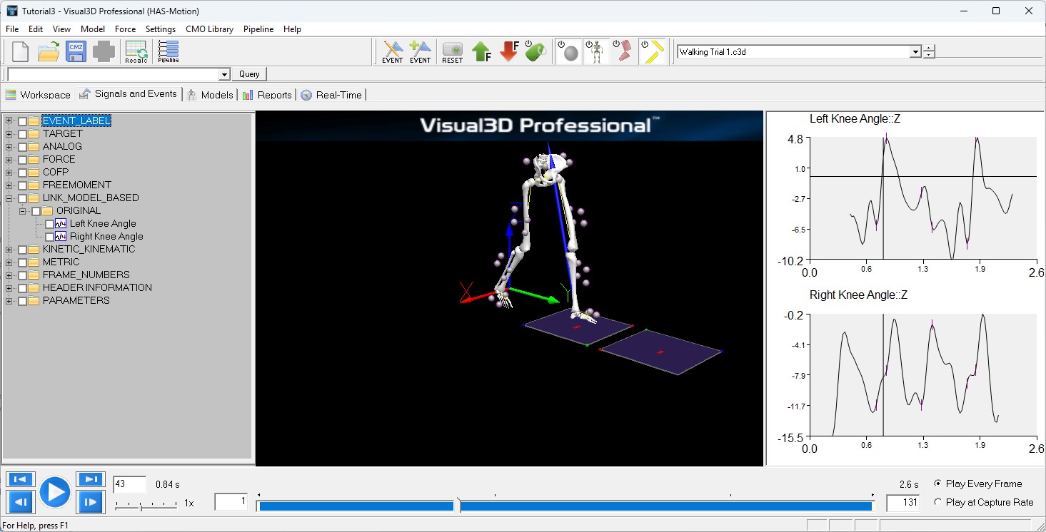
- Click on the Signal and Event Processing Tab to visualize the animation of the model based on the movement data and the model that was applied to it. If the animation doesn’t appear in the 3D Animation viewer, check the active file combo box on the toolbar. It should read 'Walking Trial 1.c3d' rather than ALL-FILES
Computing Joint Angles
Joint angles are defined as the orientation of one segment relative to another segment. Because we are dealing with 3D space, there are a series of rotational transformations involved in the calculation. A joint angle is not the same as a 3-point or 4-point angle in which there are projections, but no transformations (more on this later).
Visual3D lets you pick any 2 segments in which to measure a joint angle. They do not have to be connected – or even be near each other. In practice, joint angles are calculated as the transformation from one segment (A) to another segment (B) using the local coordinate system of segment B as the frame of reference.
It is essential that you select the proper Cardan sequence based on a complete understanding of what you are trying to measure. It is beyond the scope of this document to explain the concepts behind the 3D order of rotations/transformations that go into calculating joint angles.
In Visual3D, you can choose the Cardan sequence you want. The default Cardan sequence used by Visual3D is the ordered sequence of rotations (x, y, z) that assumes that the Z axis is in the up/down/Axial direction and the Y axis is Anterior/Posterior, or the direction if travel. (Yeadon, 1990; Davis et al., 1991; Kadaba et al., 1990), where:
X = flexion/extension
Y = abduction/adduction
Z = longitudinal rotation
One of the options for joint angles is to select normalization (not generally recommended). Normalization means that when the segments in the movement trial are in the same relative posture as the same segments in the standing trial, the joint angle is considered zero. The problem with the calculation of a normalized angle (as we have done it) is that the standing posture and the movement trial should both be aligned with the laboratory axis. Getting a patient to stand oriented relative to the lab may not be possible. An alternative approach is to create Virtual Segments that define the desired angle in the standing posture. For example, See here, or here.
Create a joint angles for the right knee
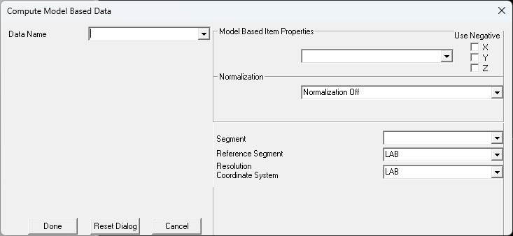
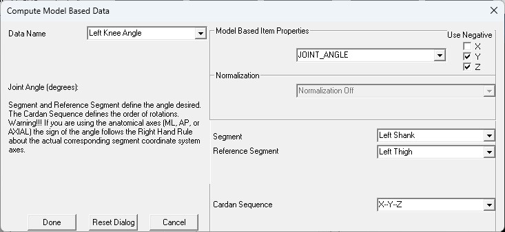
In Visual3D, from MODEL in the main menu bar, select Compute Model Based Data to get the following dialog box.
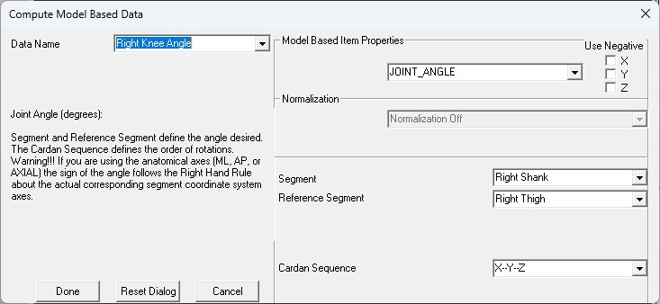
Create a joint angle called ’Right Knee Angle’ (i.e. its Data Name). The link model based property is a Joint Angle. The segment will be the right shank and the reference segment is the right thigh. Select the Cardan sequence XYZ, which for these segment coordinate systems is the equivalent of the Joint Coordinate System. Then press the Create button.
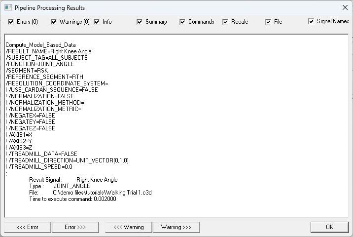
The joint angle is created and a processing dialog shows if any errors were encountered. Note that the dialog also contains which files were processed. It is important to note this because signals are only created for the active files.
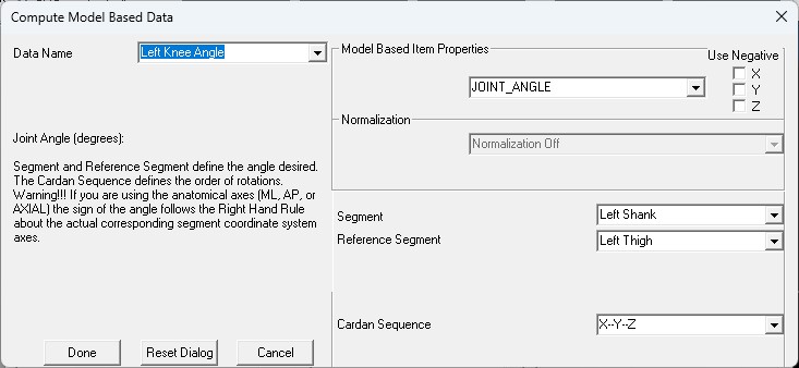
Create a joint angle called Left Knee Angle as follows:
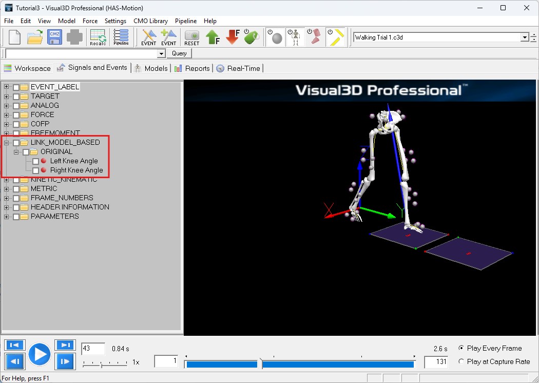
Notice that a new folder is created in the Data Tree for LINK-MODEL-BASED calculations. This folder now contains the Left Knee Angle and Right Knee Angle Signals.
Understanding the Knee Angle Signal
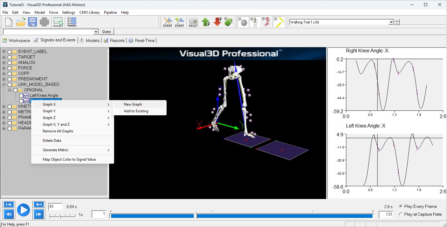
Graph the X-Component of the Right Knee Angle and Left Knee Angle signals.
For this segment coordinate system (z-up, y-anterior) rotation about the x-axis represents flexion/extension. Visual3D always computes all signals based on the Right Hand Rule.
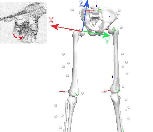
For example, if you point your thumb in the direction of the x-axis of the hip (shown in Red in the animation viewer) pointing laterally to the right. Knee extension will be zero when the thigh segment coordinate system and the shank segment coordinate system are aligned. Knee flexion will be seen as a negative angle.
Note that the x-axis for both the left and right thigh segment coordinate systems points laterally to the right. In the figure below the thumb is pointing in the direction of the x-axis, the fingers are curled in the direction of shank extension (relative to the thigh), so knee extension is a positive angle.
Using the same schema adduction of the knee is positive rotation about the y-axis for the right leg and negative rotation about the y-axis for the left leg. Inward axial rotation of the shank is a positive rotation about the z-axis for the right leg and negative rotation about the z-axis for the left leg.
This reflection of the data anatomically from right to left is a result of applying the right hand rule rigidly within Visual3D. When presenting data it is quite common for Visual3D users to negate the y and z terms for the left knee angle.
The resulting knee rotations about the z-axis (inward/outward) are positive in the same direction.
Note the difference in the median value of the left and right legs. The likely cause of this offset is a slight misalignment of the segment coordinate systems for one of the legs (although it could be real for this subject).
Computing Joint Angles for the Legs
Create the following joint angles for the lower body.
Data Name= Right Hip Angle
Folder= ORIGINAL
Model Based Item Properties= JOINT_ANGLE
Negate X, Y, Z= All Unchecked
Normalization= Normalization Off
Segment= Right Thigh
Reference Segment= Pelvis
Cardan Sequence= X-Y-Z
Data Name= Right Knee Angle
Folder= ORIGINAL
Model Based Item Properties= JOINT_ANGLE
Negate X, Y, Z= All Unchecked
Normalization= Normalization Off
Segment= Right Shank
Reference Segment= Right Thigh
Cardan Sequence= X-Y-Z
Data Name= Right Ankle Angle
Folder= ORIGINAL
Model Based Item Properties= JOINT_ANGLE
Negate X, Y, Z= All Unchecked
Normalization= Normalization Off
Segment= Right Foot
Reference Segment= Right Shank
Cardan Sequence= X-Y-Z
Data Name= Left Hip Angle
Folder= ORIGINAL
Model Based Item Properties= JOINT_ANGLE
Negate X, Y, Z= All Unchecked
Normalization= Normalization Off
Segment= Left Thigh
Reference Segment= Pelvis
Cardan Sequence= X-Y-Z
Data Name= Left Knee Angle
Folder= ORIGINAL
Model Based Item Properties= JOINT_ANGLE
Negate X, Y, Z= All Unchecked
Normalization= Normalization Off
Segment= Left Shank
Reference Segment= Left Thigh
Cardan Sequence= X-Y-Z
Data Name= Left Ankle Angle
Folder= ORIGINAL
Model Based Item Properties= JOINT_ANGLE
Negate X, Y, Z= All Unchecked
Normalization= Normalization Off
Segment= Left Foot
Reference Segment= Left Shank
Cardan Sequence= X-Y-Z
Computing Joint Moments
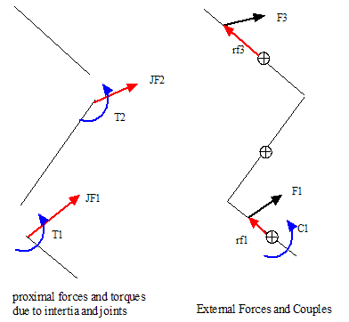
A free body diagram of two segments, showing the traditional assumptions for inverse dynamics analysis.
The Joint Force is the reaction force between adjacent segments.
- It is assumed that the joint forces are equal and opposite about the joint.
- It is assumed that joint moments are equal and opposite about the joint.
- The distal end of one segment is not assumed to be at the same point as the proximal end of the next segment. This allows movement in the ”r;joint”. Regardless of the position of the proximal end of the distal segment, we translate the force to the distal end of the proximal segment for the inverse dynamics calculations.
Note: Visual3D calculates the Net Internal Moment.
The external moment is balanced by the net internal moment produced by the muscles and ligaments. For example, a net internal moment dominated by the quadriceps muscles would be needed to balance an net external moment created by the Ground Reaction Force.
Mathematically, the external moment is equal and opposite to the internal moment, but the user is cautioned to reference the term if it is used in an article.
Note: The external moment is a term that is not commonly used.
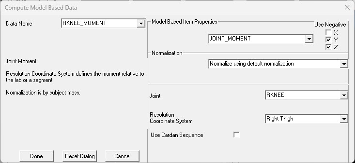
Create the Net Joint Moment for the Right Knee. The following image contains one definition of the Right Knee Moment.
The Joint RKNEE is the proximal end of the Shank Segment; This is a default joint name.
The Resolution Coordinate System is usually the segment proximal to the Joint, so in this case the Right Knee Moment is resolved in the Segment Coordinate System of the Right Thigh.
The default normalization (selected in this image) is to divide the Joint Moment by the Subject Mass. Note: that any metric value can be used for normalization.
There are four options for normalizing the Joint Moment model based signal.
Normalization Off
Normalize using default normalization
Normalization is by subject mass.
Normalize to local metric value
For example, a metric could be created containing the Mass*Height of the subject using the following command.
Multiply_Signals
/SIGNAL_TYPES=METRIC+METRIC
/SIGNAL_NAMES=MASS+HEIGHT
/SIGNAL_FOLDER=PROCESSED+PROCESSED
/RESULT_NAME=MxH
! /RESULT_FOLDER=PROCESSED
In the Compute Model Based Dialog selecting this normalization will cause a combo box to appear to allow you to select the Metric.
Normalize to GLOBAL metric value
This is similar to 3 except that the METRIC signal is assumed to be a GLOBAL signal.
Interpreting the Joint Moment Signal
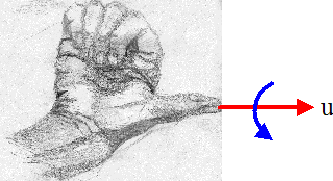
Visual3D always follows the right hand rule. The direction of positive rotation about the axis u (red arrow aligned with the right thumb) in the above figure is in the direction of curl of the fingers (blue arrow)
In order to determine the sign of the joint moment, the user must visualize the segment coordinate system that the moment is resolved into, then follow the right hand rule. For example, consider the knee moment. The typical knee moment is defined as the shank with respect to the thigh. The default segment coordinate system in Visual3D is x-lateral, y-anterior, z-axial. Therefore, knee extension moment is positive, knee adduction moment is positive, and internal rotation is positive.
The buttons for negating the signal are available for users that don't want to use the Visual3D Right Hand Rule convention. For example, some users prefer that flexion of the hip, knee, and ankle have the same sign; the Right Hand Rule would dictate that the Knee Flexion is opposite in sign to the Hip and Ankle Flexion. Selecting to negate the x-component of the Joint Moment will cause the flexion moment to have a consistent sign.
Computations based on PROCESSED signals
As presented in a previous tutorial, it is straightforward to process the target, analog, or force signals.
It is also possible to create several processed versions of a signal, so Visual3D needs a rule for determining which signals are used to create the model based signals.
If you have selected the settings option to use PROCESSED targets, the PROCESSED targets and PROCESSED FORCE, COFP, and FREEMOMENT are used for computing the model based items. If the PROCESSED signal doesn't exist, Visual3D uses the ORIGINAL folder.
The model based signals that are computed from the PROCESSED signal are still defined as ORIGINAL model based signals.

