Table of Contents
Signal Processing
The objective of this tutorial is to provide an overview of signal processing in Visual3D.
Most signal processing functionality is available through the Command Pipeline, so it is advisable that you are familiar with the material in the previous tutorial on the topic.
Data
The ZIP file Visual3D Tutorial 4 Sample Data can be downloaded for the material required to begin this tutorial. this contains:
- Tutorial4_Start: Provides a starting point for this tutorial, this .cmz was generated in the Visualizing Data Tutorial.
- Tutorial4_InterpolateFilterApplied_End.cmz: End result file from this tutorial to view for correct Signal Processing.
If you prefer, a video tutorial is available outlining the same process. It is available at this link: Visual3D Tutorial Video 4: Signal Processing
Preparation
- Open Tutorial4_Start.cmz, which can also be the same starting file for the previous tutorial, Command Pipeline. Or, that you downloaded from the introduction of this tutorial.
- Click on Signal and Event Processing to visualize the animation of the model based on the movement data and the model that was applied to it. If the animation doesn’t appear in the 3D Animation viewer, check the active file combo box on the toolbar. It should read ’Walking Trial 1.c3d’ rather than ALL_FILES
- If the animation is not playing, click on the PLAY button of the VCR controls at the bottom of the screen.
- There are many viewing options for the Animation viewer available under the View Menu item or by clicking with the Right Mouse Button in the Animation Viewer itself. You should play around with these options to see the effects they have; most of the effects are intuitively obvious.
Visual3D Philosophy
When a C3D file is loaded the data is copied into the Visual3D workspace. Visual3D follows a philosophy that your original data is sacrosanct. You should definitely check out the Visual3D Philosophy page, but we will review some key points here.
Visual3D ensures that your original data is never be changed or modified. All processing performed on signals creates a new signal, whose Processing History is stored as a property of the new signal. This protects the researcher from “losing track” of the processing that was done and allows analysis results to be reproduced at any time. The original signals are stored in a folder labeled ORIGINAL. If a signal is processed with a command that acts only on that signal (e.g. a digital filter), the result is placed into a folder labeled PROCESSED. If the ORIGINAL signal is processed again, the existing PROCESSED signal is replaced with the newer version. If the user wants to retain this PROCESSED folder with the intention of having several versions of a signal persisting (e.g. Position, Velocity, and Acceleration), the PROCESSED folder can be renamed; this renamed folder will persist (e.g. it won't be overwritten automatically).
You need to be aware of any pre-processing done by your camera or analog equipment manufacturer. Some vendors interpolate and/or filter data prior to creating an output file, perhaps in order to make their output “look better”, for commercial reasons. At HAS-Motion, we believe that this practice has potentially damaging effects on outcomes. Physical disabilities can be completely hidden or minimized in this manner. Researchers using these systems will not be able to create reproducible results without fully documenting the preprocessing assumptions, algorithms, and results prior to any analysis. Feel free to contact HAS-Motion if you are unsure about how you system generates and provides its data. In many cases, pre-processing activity can be turned off.
Being wary of unwarranted assumptions is also why we advocate capturing data in as “raw” a form as possible. For example, if all we have is pre-computed ground reaction data from a force plate as input, we have to make the (possibly unwarranted) assumption that all the force plate properties, calibrations, and processing were correct since there is no way to validate the data. In building Visual3D, and in our attempts to improve it incrementally over time, we have tried to make working with raw input data as painless as possible in order to encourage you to do so.
We have been challenged on this notion of the raw data because Visual3D doesn't actually work with the video images, but rather with the processed 3D trajectories from another program. We accept this limitation but point out that most manufacturers place the calibration and tracking parameters into the C3D File.
Interpolate and Filter TARGET signals using the Graphical Interface
Several basic signal processing functions are available interactively by selecting a second tier FOLDER (e.g. TARGET:ORIGINAL, ANALOG:PROCESSED, etc) in the data tree with the Right Mouse Button. The available functions are:
- Lowpass Filter
- Highpass Filter
- GCVSPL
- DFT
- Interpolate
- Rectify
Interpolating and Filtering TARGET data is a two-step process. The available functions in the graphical user interface can be used to complete this process.
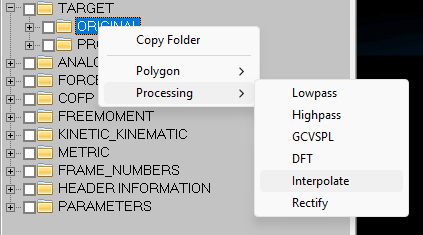
- Expand the data tree in Signal and Event Processing mode.
- With the Right Mouse Button select the ORIGINAL folder under the TARGET folder.
- With the Left Mouse Button select the interpolate option.
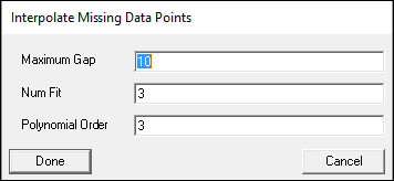
- Select Done to execute the command.
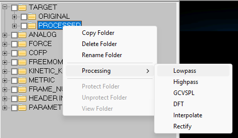
Note that a PROCESSED folder has appeared under the TARGET folder in the data tree.
- With the Right Mouse Button select the PROCESSED folder under the TARGET folder.
- With the Left Mouse Button select the lowpass option.
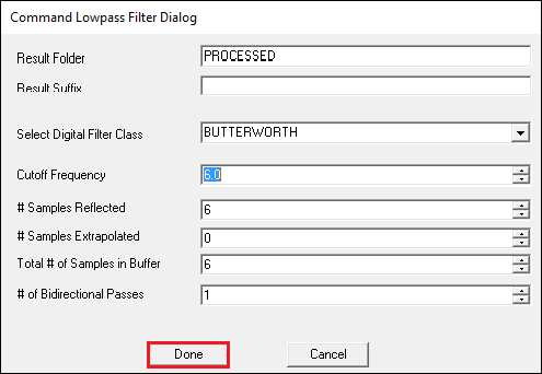
- Select Done to execute the command.
See Pipeline Command Syntax Tutorial for an explanation of the default command parameters.
- Note that only a PROCESSED folder exists under the TARGET folder in the data tree (e.g. a new PROCESSED folder wasn't created). By default Visual3D uses only one PROCESSED folder, which contains the most recent processing done to a signal.
- Expand the PROCESSED folder in the data tree and with the Left Mouse Button select the signal LFT1. A dialog appears containing 3 tabs. Selecting the History tab will display a list of the processing steps that have been applied to this signal

- If you want to protect the PROCESSED folder so that it is not replaced by the next processing step, you should rename it to something else. A folder with a name other than PROCESSED will not be removed unless the user explicitly deletes it.


Interpolate and Filter the TARGET signals using the Command Pipeline
Interpolating and Filtering TARGET data can also be accomplished using the Command Pipeline.
NOTE: This section and the previous section should not BOTH be done. If you have already manually interpolated and filtered the data, then you should not also do so with the command pipeline.
- Launch the Command Pipeline Dialog by clicking the pipeline button
 on the toolbar, or by pressing F11.

- Expand the TARGET folder in the data tree (in Signal and Event Processing Mode) and select the check box beside the ORIGINAL folder.
- Expand the Signal Process folder in the list of Pipeline Commands
- Double click on the Interpolate to load the command into the pipeline
- Click on Import Checked Signals (With Prefix) button, which will add the checked signals to the pipeline command.

- Select the Execute Pipeline button to execute the interpolate command.
- When you execute the pipeline, Visual3D executes in order all commands in the pipeline. A dialog will appear with the results of the processing. It lists the output of each command and highlights any errors. Pipelines are useful for ordering a set of tasks so that they always occur in the same order. But pipelines must be set up precisely in order to work.
- A PROCESSED folder will appear in the TARGET folder in the Data Tree.

- Expand the TARGET folder in the data tree (in Signal and Event Processing Mode) and select the check box beside the PROCESSED folder.
- Expand the Signal Filter folder in the list of Pipeline Commands
- Double click on the Lowpass_Filter to load the command into the pipeline
- Click on Import Checked Signals from Tree button, which will add the checked signals to the pipeline command.

- Select the Execute Pipeline button to execute the interpolate command.
- A dialog will appear with the results of the processing
- A new PROCESSED folder will not appear in the TARGET folder in the Data Tree because the existing PROCESSED folder has now been updates to contain signals that have been Interpolated and Filtered. Check the signal processing history as described in the previous section.


Signal Math
The Signal Math commands in the pipeline are mostly related to mathematical operations on signals, such as multiplying two signals.
If the processed signal is result of a command that includes more than one signal (e.g. adding two signals), it is not appropriate to store the new signal as a PROCESSED version of either one of the signal used. In this situation Visual3D stores the resulting signal into a folder labeled DERIVED. The user should be careful with DERIVED signals because they contain a variable number of components (e.g. 1 if ANALOG signals were used, 2 if TARGET signals were used, etc.)
The most powerful Signal Math Command is Evaluate_Expression
For example, to compute the absolute value of multiplying 2 signals use the following.
Evaluate_Expression
/Expression= abs(ANALOG::ORIGINAL::EMG1 * ANALOG::ORIGINAL::EMG2)
/Result_Name=EMG_MULT
/Result_Type=DERIVED
/Result_Folder=PROCESSED
;
Proceed with next Tutorial: Force Platforms