Building a 6 DOF Model
This is the first tutorial in the Visual3D typical processing session, each of the tutorials will go over the sequence of steps involved in handling and analyzing data in the application. This specific tutorial will go over building a 6 DoF Model from a motion capture dataset.
The techniques learned here will be consistent with all Visual3D models. However the model described in this tutorial is only designed to illustrate the principles of model building and should not be considered the Default Visual3D lower-body model. Once the user learns the basics of building models, it is up to them to decide what model and marker set is most appropriate for their analyses.
If you prefer, a video tutorial is available outlining the same process. It is available at this link: Visual3D Video Tutorial 1: Building a 6 DOF Model.
There are 6 basic steps to performing an analysis of motion capture data in Visual3D:
- Create a model of your subject using a standing trial and define the linked segments
- Explore your movement trials, and associate them with your model
- Perform any signal and event processing required
- Define any biomechanical model-based calculations (joint angles, moments, powers, etc.)
- Generate the desired reports
- If desired, export data for statistical processing
In this tutorial we will:
- Load a standing calibration trial
- Define various segments to create a lower-body a gait model.
Key Concepts
A calibration file (often referred to as a Standing Trial or a Static Trial) is a short motion capture of the subject in a stationary pose. Marker positions are averaged automatically over all frames to compensate for noise in the data. NOTE: If the subject moved during the standing trial, you can specify a subset of frames using the Modify Frame Range For Static Calibration command from the Model Menu items.
Preparing for the Tutorial
1. Ensure that version 3.0 or later of Visual3D has been downloaded and installed.
2. Download the Visual3D Tutorial 1 Sample Data.
3. Save this file in the folder where you plan to save your motion capture files.
NOTE: The download contains the end result of this tutorial. It may be useful as a secondary resource for verifying your progress.
4. Launch the Visual3D program from the Start menu.
The program will open to the main workspace.
Update: If you are working through the "Modelling Decisions affecting outcomes" tutorial, then the starting .cmz file can be downloaded here:
Before completing this tutorial please review the 3D Viewer Animation Controls.
Create a Hybrid Model
|
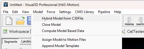
1. From the Model menu, select Create -> Hybrid Model from C3D file.
|
|
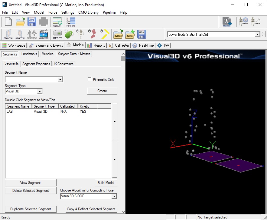
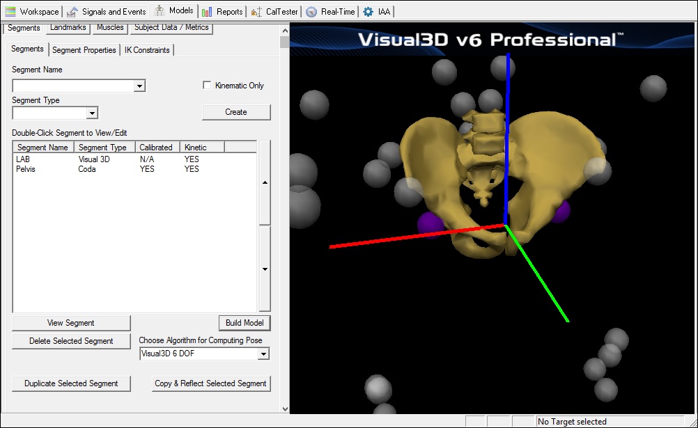
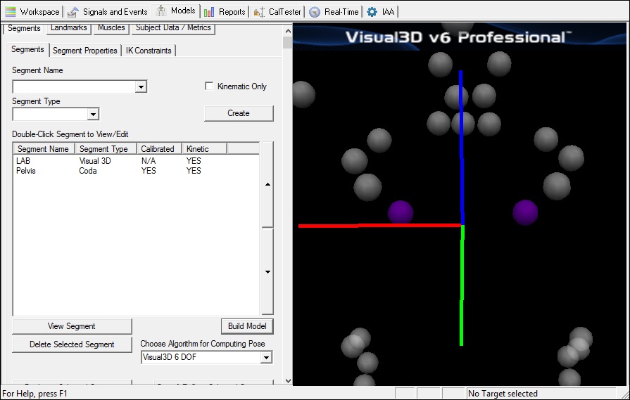
3. Visual3D will switch to Model Building mode automatically. The 3D viewer will display the average value of the marker locations from the standing file. The dialog bar to the left of the screen will contain a list of segments, which by default will contain only a segment representing the Laboratory (e.g. Motion Capture Volume). |
3D View Options
Throughout this tutorial, play with some of the 3D view options to familiarize yourself with these options:
With your mouse, use the 3D Viewer Animation Controls. to rotate/pan your view of the model.
|
1. Click the View Target ID toggle button on the toolbar until the target names appear. |
|
2. Click the View Segment toggle button on the toolbar until the pelvis bone disappears (the same effect can be achieved by pressing F5 on your keyboard). |
|
3. Click the View Segment Geometry toggle button on the toolbar until you toggle off geometric view the pelvis (the same effect can be achieved by pressing F7 on your keyboard). |
|
4. Click the View Segment Lines toggle button on the toolbar until you toggle off the yellow lines which connect the segment end points. |
Creating the Pelvis Segment
There are many possible markers for a pelvis segment that make sense anatomically, and have a history in the biomechanics community. Visual3D offers 3 default pelvis segments:
1) Visual3D Pelvis - The default pelvis segment in Visual3D is labeled a Visual3D Pelvis since the pelvis can be constructed as any other segment. Visual3D inherited this definition from MOVE3D (the precursor software to Visual3D) and has been used by the staff in the Physical Disabilities Branch at the NIH for more than 20 years.
2) CODA Pelvis - The CODA pelvis defines the location of the Hip Joint Centers using regression equations from the Bell and Brand articles.
3) Helen Hayes (Davis) Pelvis - The Helen Hayes (Davis) pelvis defines the location of the Hip Joint Centers using regression equations from the Davis article.
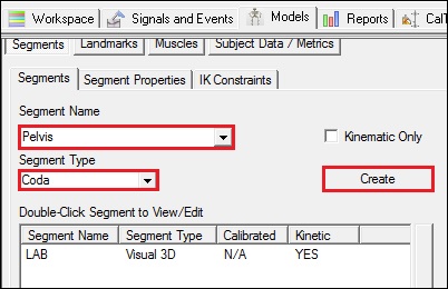
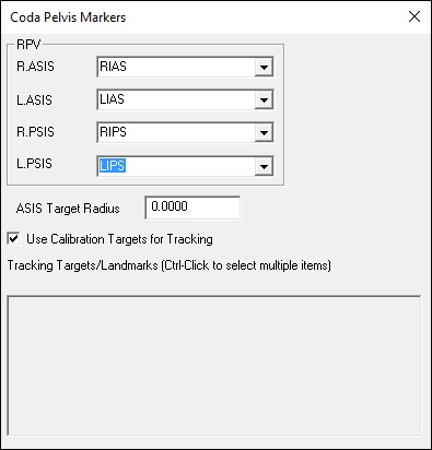
In this tutorial we are presenting the CODA pelvis:
|
1. On the segments tab:
|
|
2. In the Coda Segment Markers dialog box, enter these values:
|
|
3. Click Build Model to build the segment. You should now see a pelvis segment on your standing model. If you do not see the pelvis segment after clicking Build Model, double check the values you entered in the last step. |
View the Pelvis Segment Coordinate System
Segment Properties
At this point, the Segment Properties for the Pelvis can be modified if you would like. More information about Segment Properties, can be found here.
A little fun with the Graphics
You may skip to this section if you wish. It is possible to replace the ”bones” with another bone or object file. As a ridiculous example, you can change the pelvis model to display a skull rather than the pelvis bones. This example can be found here.
Save the data
Save often to prevent loss of files due to power outages or Windows errors.
Save the Workspace to a .cmz file
Maintain a series of .cmz files as you work so that you can revert to a previous step.
- From the File menu, click on Save As.
- In the Save As dialog box label your file MyTutorial1.cmz, navigate to the location of your choice and click Save.
Save the Model Template
- Save the segment definitions as a model template (mdh) file to allow you to re-create models using the same marker set.
- From the Model menu select Save Model Template.
- In the Save As dialog box label your file Tutorial_ModelTemplate.mdh, navigate to the location of your choice and click Save.
Apply the Model Template
- Now that the model template exists, you can use this template on other data sets.
- From the Model menu select Apply Model Template
- In the dialog box select the appropriate .mdh file.
Define the Remaining Segments
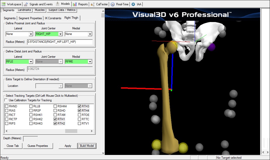
Create the Right Thigh Segment
|
1. Create Thigh Segment:
|
Create the Right Shank Segment
|
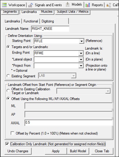
1. Create Virtual Knee Joint Center:
|
|
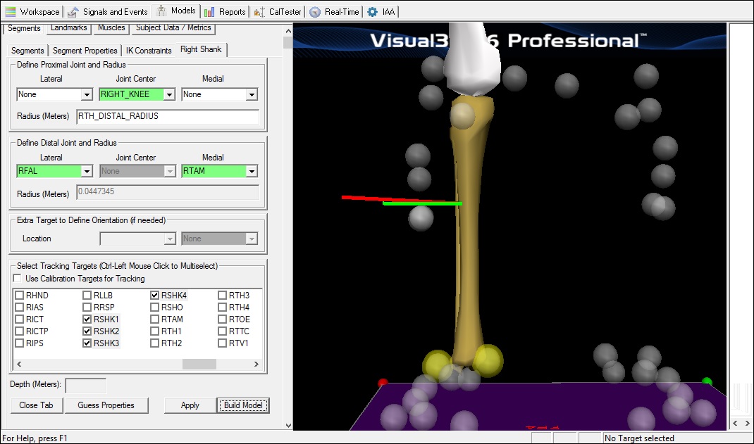
2. Create Shank Segment:
|
Create Right Foot Segment
|
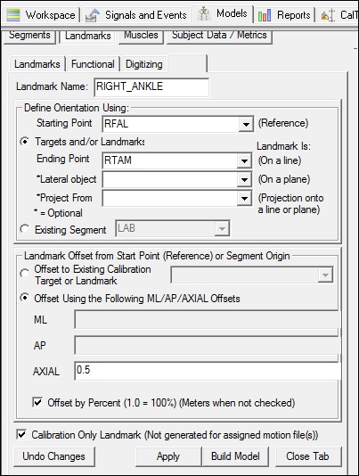
1. Create Virtual Knee Ankle Center:
|
|
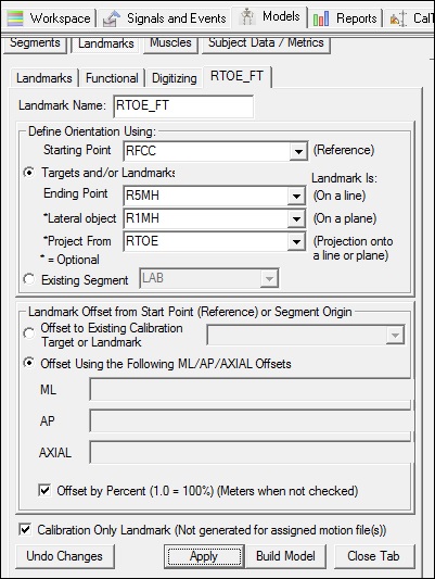
2. Create Virtual Toe Ankle Center:
|
|
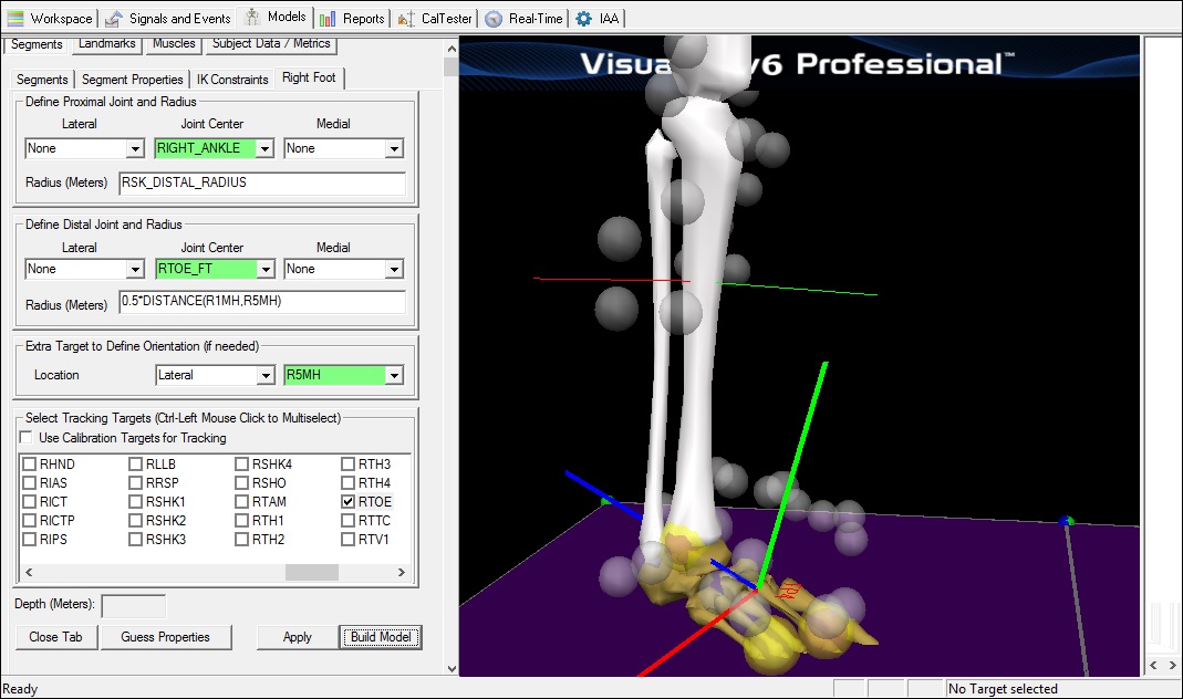
3. Create Foot Segment:
|
Create the Left Thigh Segment
|
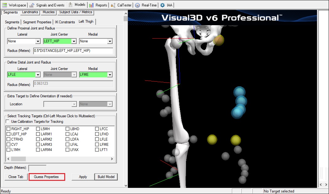
1. Create Thigh Segment:
|
Create Landmarks for Left Segments
|
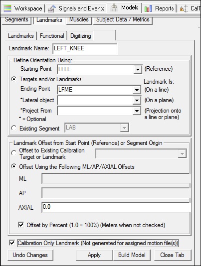
1. Create Virtual Knee Joint Center:
|
|
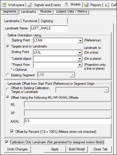
2. Create Virtual Knee Ankle Center:
|
|
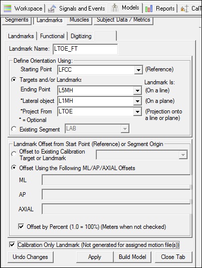
3. Create Virtual Toe Ankle Center:
|
Create the Left Shank Segment
|
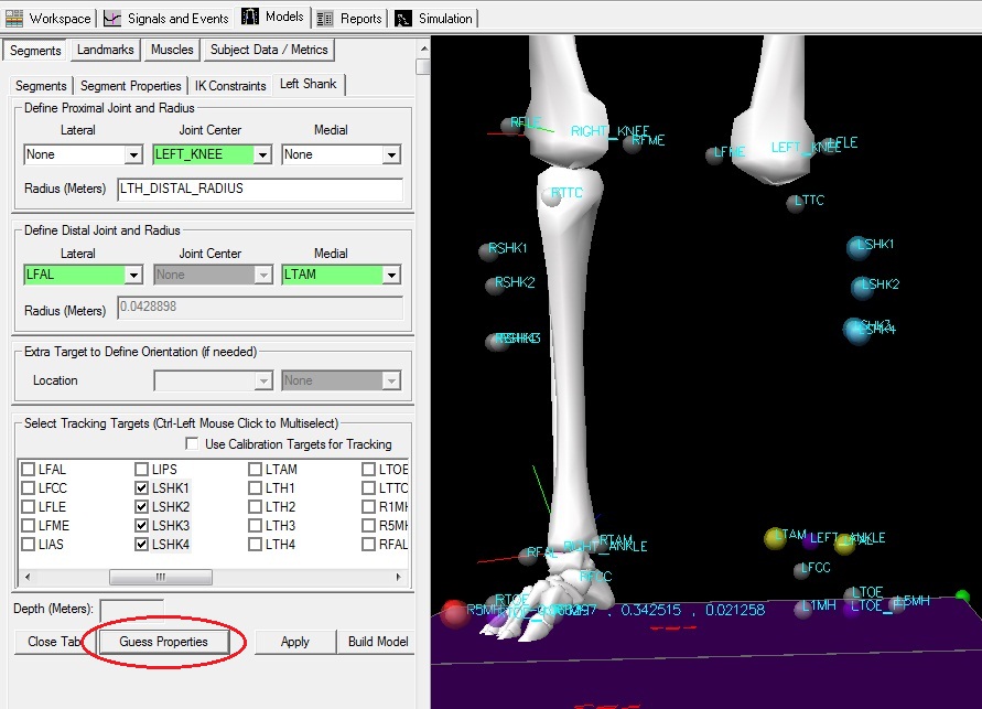
1. Create Shank Segment:
|
Create the Left Foot Segment
|
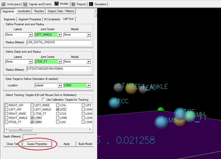
1. Create Foot Segment:
|
Create Kinematic Only Foot Segments
Kinematic Only feet are often created for more clinically relevant ankle joint angles.
For more information about kinematic only foot segments, please go here.
Completing the Model
- When all segments have been defined, click on Build Model.
- In the File menu, click on Save to save the file for use in another tutorial.
- Save the template as Tutorial_ModelTemplate.mdh.
Verify the model template
- Clear the Visual3D Workspace - Select File New
- Repeat the initial steps in this tutorial.
- Open the movement trial
- Create a hybrid model using the standing trial
- Assign the movement trial to the model
- Apply the model template. You will find this option under the Model Menu Item.
Proceed to next Tutorial: Visualizing Data

