visual3d:tutorials:modeling:building_a_6_dof_model_-_segment_properties
Table of Contents
Building a 6 DOF Model- Segment Properties
Segment Properties
The following properties are computed based on the calibration of the segment proximal and distal endpoints.
- Segment Length - This is computed based upon the calibration of the segment proximal and distal endpoints.
- Inertial Values - This is computed based upon the segment mass and geometry. These values may be modified only for segments with a CUSTOM SEG (ment) selected for the Segment Geometry.
- Distance from CM (Center of Mass) to Proximal end - This is a multiplier used to modify the distance from the center of mass from the segment's proximal end. This field is only used when CUSTOM SEG (ment) is selected for the Segment Geometry.
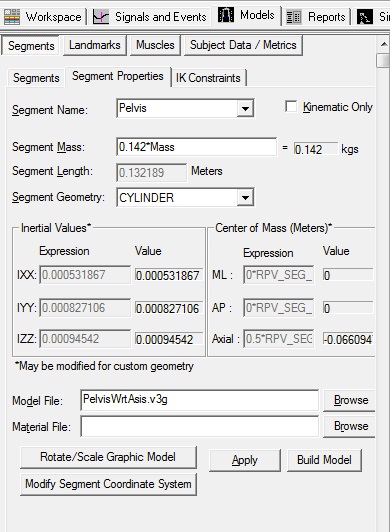
View the Pelvis Segment Properties
The Segment Properties dialog modifies general properties which are common to most segments. Some of the most common uses include changing the mass of the segment, the scale and rotation of the object which represents the segment, adding a custom object (such as a golf club or baseball bat), removing the kinetic calculations for a segment, modifying the size and rotation of the segment, and modifying the segment coordinate system.
Segment properties that may be modified
- Segment Name - Changing this will select another segment to modify.
- Kinematics Only - Use this check box for segment where only kinematics need to be calculated (where kinetic calculations are not needed). This is sometimes useful when you want to create a virtual segment where kinetic calculations are not needed such as a virtual foot or virtual lab.
- Segment Mass - The segment mass is defaulted based on the type of segment and the subject mass. To change this value, you may type in a specific value for the mass (in kilograms), or use a formula using existing Subject Data (such as a percentage of the subject Mass). This may be helpful if the subject is using a prosthesis that would have a different mass than the part of the body it replaces.
- Segment Geometry - The segment may be represented internally as a CONE, .CYLINDER, SPHERE, ELLIPSOID or CUSTOM SEG (ment). The geometry of a segment affects the segment's inertial properties and center of mass location. This also affects the segment geometry drawn when view segment geometry is selected in the animation/model builder window. This would be useful if you have a custom segment defined and need to change the default segment geometry.
- Model File - This is the graphic model file (.v3g, .obj, or .wrl) used to draw the segment in the animation/model window. In most cases this would be a bone, but could also be an object such as a golf club, baseball bat, or as you will see in the Just for Fun section below, where a skull is substituted for the pelvis, any object file.
- Material File - Material files can be loaded to change the color of a segment. Material file can only be used with .obj files.
Modify a segment's properties:
visual3d/tutorials/modeling/building_a_6_dof_model_-_segment_properties.txt · Last modified: 2024/11/15 17:43 by wikisysop

