Table of Contents
Modeling the Thorax
This page covers how to implement two different models of the thorax using Visual3D.
Thorax consistent with ISB recommendation
This tutorial describes how to model the Thorax based on the ISB recommendation.
Wu, G. et al. ISB recommendation on definitions of joint coordinate systems of various joints for the reporting of human motion - Part II: shoulder, elbow, wrist and hand. Journal of Biomechanics 38, page 981-992, 2005.
Note: Minor changes were made to the recommendation to facilitate its implementation in Visual3D and for consistency with other commonly used coordinate systems. Users are encouraged to adapt these to their own needs and requirements. The following should mainly be used as a starting point, and not as the only way to define the Thorax segment.
Anatomical Landmarks
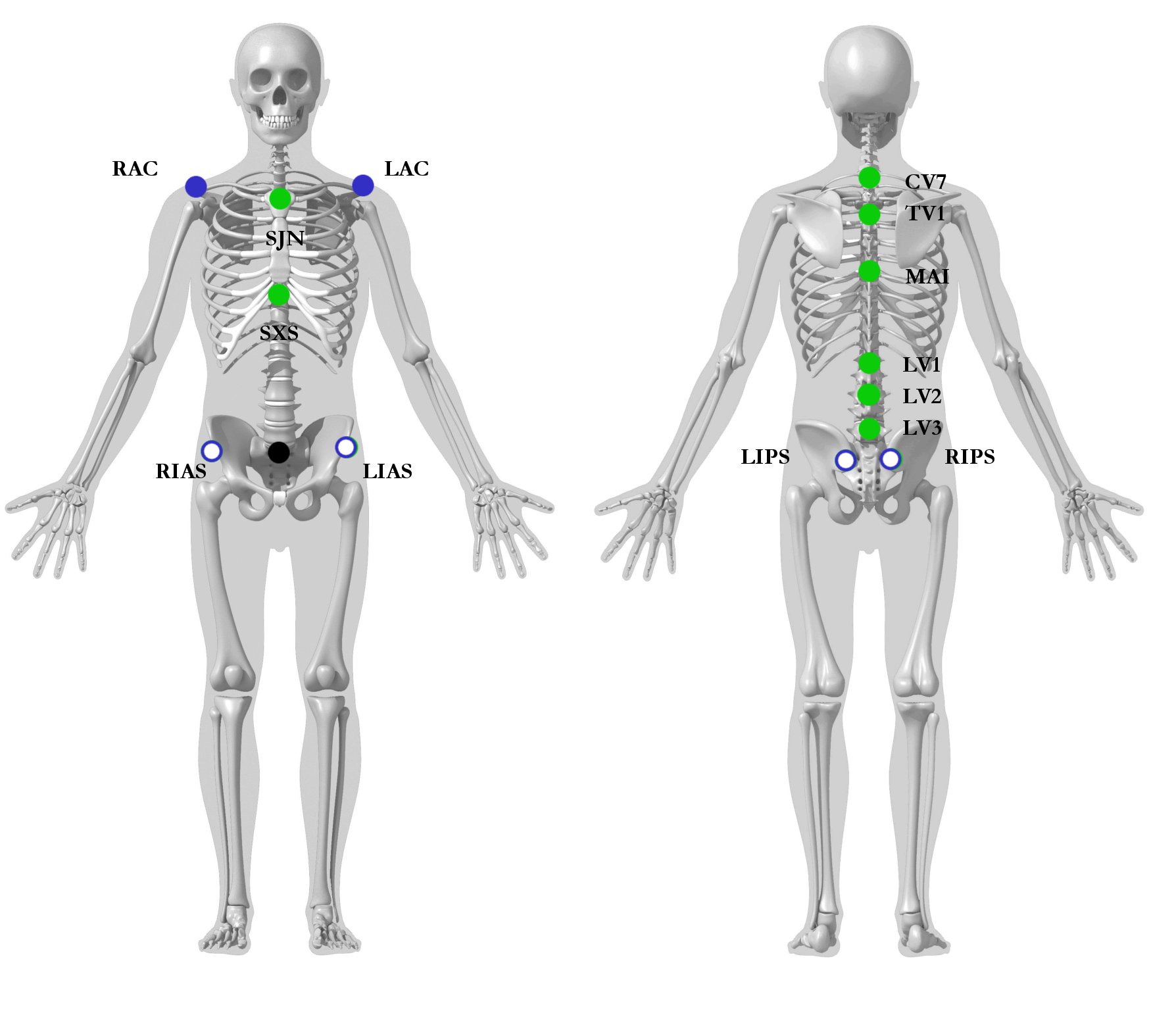
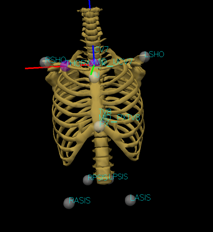
CV7: Spinal process of the 7th cervical vertebra
TV8: Spinal process of the 8th thoracic vertbebra
IJ: Deepest point of the suprasternal notch (Incisura Jugularis)
PX: Xiphoid process, most caudal point on the sternum
Note: CV7 can be replaced by the second thoracic vertebra (TV2) if required. TV8 can also be replaced either by the tenth (TV10) or twelfth (TV12) thoracic vertebra, or the mid-point between the lowest aspect of the scapula.
Quick Trick: If a lower posterior thorax marker is used, but not require to be placed on a specific anatomical landmark, a quick, consistent and reliable way to place this marker is as followed:
With the subject standing up, ask them to place one of their arms behind their back with their elbow flexed at 90 degree, so that their forearm crosses their spine in a perpendicular manner. Place the lower posterior thoracic marker on the spine, “2 fingers” above their arm.
Technical Coordinate system Xt, Yt, Zt
Origin: The origin coincident with the mid-point between IJ and CV7.
Xt: The line perpendicular to the plane formed by IJ, CV7, and the midpoint between PX and T8, pointing to the right.
Yt: The common line perpendicular to the Zt- and Xt-axis, pointing forwards.
Zt: The line connecting the midpoint between PX and T8 and the midpoint between IJ and CV7, pointing upward.
Visual3D Model Construction
The file Thorax_Static.c3d can be downloaded for this tutorial. Alternatively, you can also use your own data, with a similar markerset.
Landmarks need to be created for: midpoint of IJ and CV7 (MID_IJCV7), midpoint of PX and TV8 (MID_PXTV8) and THORAX_X.
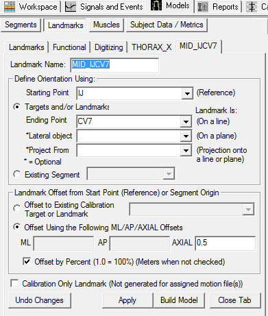
To create the midpoint of IJ and the CV7 landmark MID_IJCV7:
- Click on the Landmarks TAB
- Click on Add New Landmark tab
- In the Landmark Name box, enter MID_IJCV7
- In the Starting Point box, enter IJ
- In the Ending Point box, enter CV7
- From the Offset Using the Following AP/ML/Axial Offsets box, in the AXIAL enter 0.5
- Check the Offset by Percent (1.0=100%) (Meters when not checked)
- Click Apply.
To create the midpoint of PX and the TV8 landmark MID_PXTV8:
- Click on Add New Landmark tab
- In the Landmark Name box, enter MID_PXTV8
- In the Starting Point box, enter PX
- In the Ending Point box, enter TV8
- From the Offset Using the Following AP/ML/Axial Offsets box, in the AXIAL enter 0.5
- Check the Offset by Percent (1.0=100%) (Meters when not checked)
- Click Apply.
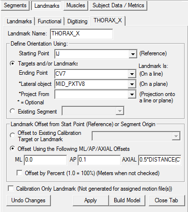
To create the lateral Thorax landmark used to define the medio-lateral axis THORAX_X:
- Click on Add New Landmark tab
- In the Landmark Name box, enter THORAX_X
- In the Starting Point box, enter IJ
- In the Ending Point box, enter CV7
- In the Lateral object box, enter MID_PXTV8
- From the Offset Using the Following ML/AP/Axial Offsets box, in the AP enter 0.1 AXIAL enter 0.5*DISTANCE(IJ,CV7)
- Click Apply.
We have now created all the needed landmarks for the Thorax/Ab segment. To create the Thorax/Ab segment in Visual 3D:
- Click on Segments tab
- From the Segment Name box, select Thorax/Ab.
- From the Segment Type box, select Visual 3D.
- Click Create.
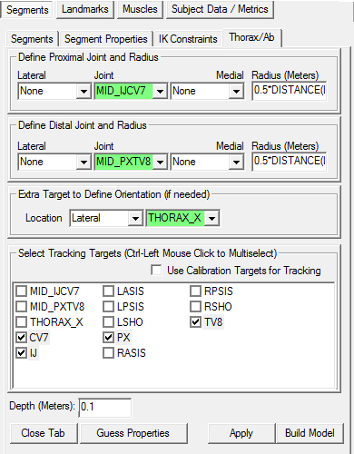
A dialog will open that will allow us to define the segment. The Z axis, pointing upwards, is the predominant axis. This is defined as the direction from the midpoint of the PX and TV8 to the midpoint of IJ and CV7. The proximal and distal ends of the segment must be defined. The origin is the MID_IJCV7.
- In the Define Proximal Joint and Radius section, select MID_IJCV7 for the Joint.
- In the Proximal Radius box, enter 0.5*distance(LSHO,RSHO).
- In the Define Distal Joint and Radius section, select MID_PXTV8 for the Joint.
- In the Distal Radius box, enter 0.5*distance(LSHO,RSHO)
- In the Extra Target to Define Orientation section, select Lateral for the Location. and THORAX_X for the marker.
- In the Select Tracking Targets, click on CV7, IJ, PX, and TV8
- In Depth, enter 0.14
- Click on Build Model
Scaling the thorax's graphic
You should now see a thorax segment on your standing model. The thorax graphic is not oriented or scaled correctly. If you do not see the thorax segment after clicking Build Model, double check the values you entered in the last step. We now need to rotate the thorax graphic to the correct orientation. To orient the thorax skeleton graphic.
- Click on the Segment Properties TAB
- Click on Rotate Scale/Graphic Model tab
- Rotate the scale/graphic 180 in vertical rotation.
- Click on Scale button
- Change the scale for all three (width, depth and height) to 180
- Click on the Move button
- Change the Move Up/Down to 65
- Click on Ok
- Click on Apply
Note: The scaling and position (move) values are specific to this tutorial's dataset. The values may vary if using your own dataset.
ISB's exact coordinate system
Once the above Thorax segment has been created, it is very easy to create another Thorax segment to the ISB's exact specifications.
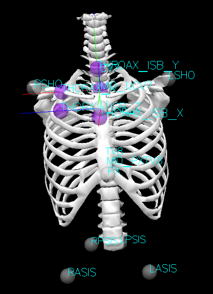
Two additional landmarks have to be created, THORAX_ISB_Z and THORAX_ISB_Y:
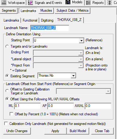
To create the THORAX_ISB_Z landmark:
- Click on the Landmarks TAB
- Click on Add New Landmark tab
- In the Landmark Name box, enter THORAX_ISB_Z
- In the Starting Point box, enter IJ
- In the Existing Segment box, select Thorax/Ab
- From the Offset Using the Following AP/ML/Axial Offsets box, in the ML enter 0.1
- Click Apply.
To create the THORAX_ISB_Y landmark:
- Click on the Landmarks TAB
- Click on Add New Landmark tab
- In the Landmark Name box, enter THORAX_ISB_Y
- In the Starting Point box, enter IJ
- In the Existing Segment box, select Thorax/Ab
- From the Offset Using the Following AP/ML/Axial Offsets box, in the AXIAL enter 0.1
- Click Apply.
Once these two landmarks have been created,
- In the Define Proximal Joint and Radius section, select IJ for the Joint.
- In the Proximal Radius box, enter 0.5*distance(LSHO,RSHO).
- In the Define Distal Joint and Radius section, select THORAX_ISB_Y for the Joint.
- In the Distal Radius box, enter 0.5*distance(LSHO,RSHO)
- In the Extra Target to Define Orientation section, select Lateral for the Location. and THORAX_ISB_Z for the marker.
- In the Select Tracking Targets, click on CV7, IJ, PX, and TV8
- In Depth, enter 0.14
- Go to the Segment Properties tab
- Select THORAX_ISB in the Segment Name list
- For Segment Mass, enter 0.1.
- For Segment Geometry, select Cone from the list
- Click Apply
- Click on Build Model
In the Segment Properties tab, select THORAX_ISB from the Segment Name box.
- Click on Modify Segment Coordinate System
- For the A/P Axis, select -X
- For the Distal to Proximal axis, select -Y
- Click OK
RAB Thorax Model
Model based on the upper extremity model developed by Dr. George Rab, Kyria Petuskey, and Anita Bagley from Shriners Hospital for Children, Northern California. Refer to their paper “A Method for Determination of Upper Extremity Kinematics” Gait & Posture 15 (2002) 113-119 for the exact model specifics (Download here). Another article using the Rab upper body model can be downloaded here.
The Thorax/Ab segment is constructed from virtual landmarks on the lateral superior borders of the Iliac Crest and virtual landmarks at the shoulder joint centers.
Iliac Crest Landmarks
The Iliac Crest Landmarks were estimated using the Terry Database published as:
Kepple TM, Sommer HJ, Siegel KL, Standhope SJ (1998) A three-dimensional musculoskeletal database for the lower extremities. Journal of Biomechanics 31, pp 77-80 This landmark was not part of the original Terry Database, but we estimated the position from the database that can be downloaded Here.
The medial/lateral and superior/inferior location of the RIGHT_ILIAC and LEFT_ILIAC landmarks were defined as the most lateral point on the superior tubercle of the Iliac crest (landmarks 39 & 40 of the Terry Pelvis dataset)
The anterior/posterior location of the RIGHT_ILIAC and LEFT_ILIAC landmarks were defined as the lateral surface of the Right ilium at midpoint between most lateral point on superior tubercle of the Iliac crest and origin of the Gluteus Medius posterior fibers {landmarks 43 & 44 of the Terry Pelvis dataset)
The location of Terry Landmark 39 is (22.332 , -54.477 , 29.705)
The location of Terry Landmark 40 is (-251.082 , -49.732 , 36.540)
These values were averaged for creating the landmark.
From the Terry dataset the distance between the ASIS landmarks (Terry landmarks 1&2) is approximately 228 which is defined as the x-axis of the pelvis.
The x-component of the RIGHT_ILIAC landmark in Pelvis coordinates is (114+22.7)*ASIS_DISTANCE/228
The z-component of the RIGHT_ILIAC landmark in Pelvis coordinates is (33.1)*ASIS_DISTANCE/228
From the Terry dataset the perpendicular distance from the x-axis to the mid-point of the PSIS landmarks (Terry landmarks 3&4) is approximately 143.5
In Visual3D create a Subject/Model Metric to compute this distance as the distance from the SACR marker to the mid-point of the RASI and LASI markers.
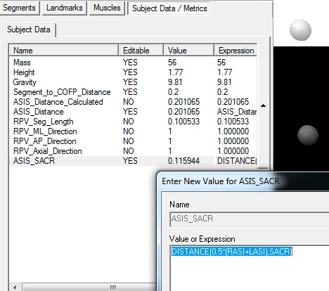 The y-component of the RIGHT_ILIAC landmark in Pelvis coordinates is (-54.477)*ASIS_SACR/143.5
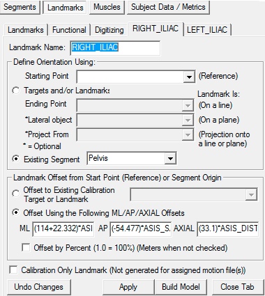
Create the RIGHT_ILIAC Landmark using these values as.
 In Summary:
The RIGHT_ILIAC landmark is defined as:
Existing Segment= Pelvis
ML= (114+22.332)*ASIS_DISTANCE/228
AP= (-54.477)*ASIS_SACR/143.5
AXIAL= (33.1)*ASIS_DISTANCE/228
The LEFT_ILIAC landmark is assumed to be located symmetrically and defined as:
Existing Segment= Pelvis
ML= -(114+22.332)*ASIS_DISTANCE/228
AP= (-54.477)*ASIS_SACR/143.5
AXIAL= (33.1)*ASIS_DISTANCE/228
Construct the segment
We have now created all the needed landmarks for the thorax/ab segment. To create the thorax/ab segment in Visual 3D:
- Click on Segments tab
- From the Segment Name box, select Thorax/Ab.
- From the Segment Type box, select Visual 3D.
- Click Create.
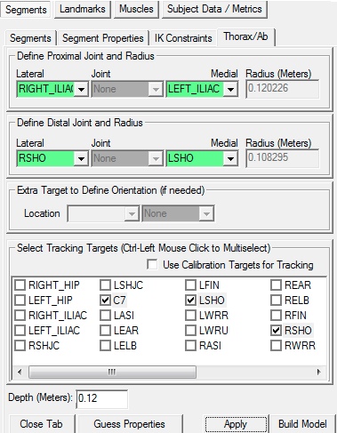
A dialog will open that will allow us to define the segment.
- In the Define Proximal Joint and Radius section, select RIGHT_ILIAC for the Lateral. and select LEFT_ILIAC for the Medial.
- In the Define Distal Joint and Radius section, select RSHO for the Lateral. and select LSHO for the Medial.
- In the Select Tracking Targets, click on C7, STRN, LSHO, RSHO
- In the Depth (Meters): box, enter 0.12
- Click on Build Model
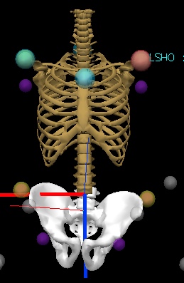
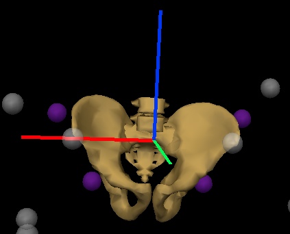
You should now see a thorax segment on your standing model. If you do not see the thorax segment after clicking Build Model, double check the values you entered in the last step.
Note that the Z-axis of the segment (Blue Line) is pointing down, so we must fix that.
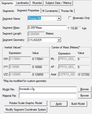
Switch to the segment properties tab, select the Thorax/Ab segment in the combo box, and select Modify Segment Coordinate System.
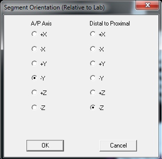
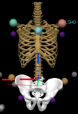
Select the AP direction to be -Y and the AXIAL direction to be -Z
This may seem a little strange at first because it is certainly an option to create the segment with the Acromion at the proximal end and the Iliac Crest at the distal end.
Placing the proximal end of the thorax/ab segment at the pelvis essentially places two proximal ends together (e.g. the Thorax/Ab and Pelvis), but now the distal end of the Thorax/Ab segment is at the shoulders, which allows the creation of shoulder and neck joints (e.g. the arms and head are considered distal segments of the body).
References
ISB Thorax: Wu, Ge, et al. “ISB recommendation on definitions of joint coordinate systems of various joints for the reporting of human joint motion—Part II: shoulder, elbow, wrist and hand.” Journal of biomechanics 38.5 (2005): 981-992.
RAB Thorax: Rab, George, Kyria Petuskey, and Anita Bagley. “A method for determination of upper extremity kinematics.” Gait & posture 15.2 (2002): 113-119.

