User Tools

Site Tools


visual3d:tutorials:modeling:virtual_laboratory

Virtual Laboratory


A segment coordinate system in Visual3D does not have to be associated with the subject, or even with motion capture data for that matter. We refer to these as virtual segments. The only distinction between virtual segments and real segments is that typically we set them to be Kinematic only segments, which means that they are not included in the Inverse Dynamics calculations. In all other ways they are just segments and are constructed with the same rules as all segments.

Example: Simple Virtual Laboratory

A Virtual Laboratory is not a physical segment in Visual3D but is equivalent to a physical segment to the effect that it has a Segment Coordinate System that can be used to represent the laboratory (or other objects) and has an associated surface model that can be animated as part of the scene. A typical use of the Virtual Laboratory is to represent the floor so that motion capture markers can be projected onto the floor.

Note: A typical use of the Virtual laboratory is for creating Normalized Joint Angles and Normalized Segment Angles.

Below is a straightforward virtual lab that has a specified constant orientation.

An example of the Simple Virtual Lab can be downloaded here.

Create 4 Landmarks

First, create 4 landmarks Lab_Origin, Lab_X, Lab_Y, and Lab_Z. To create these landmarks, go to the Model tab and select the Landmarks tab.


1. Create Lab_Origin:


  1. Click Landmarks button


  2. Click Add New Landmark button


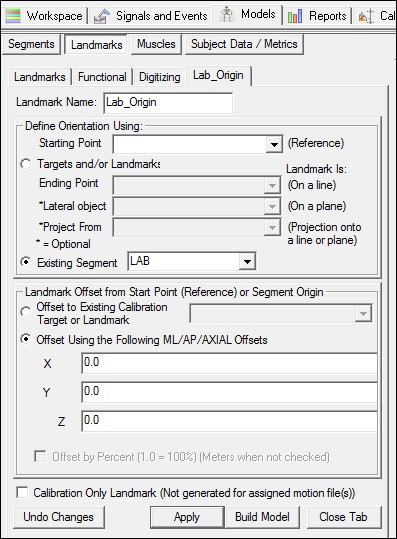
  3. Create Landmark: Lab_Origin

       Landmark Name: Lab_Origin


       Define Orientation Using:
       Starting Point: Leave Blank
       Existing Segment: LAB


  4. Offset Using the Following ML/AP/AXIAL Offsets:
       X: 0.0    Y: 0.0    Z: 0.0


  5. DO NOT Check: Offset by Percent (1.0 = 100%)


  6. DO NOT Check: Calibration Only Landmark

    vlab_lab_origin.jpg

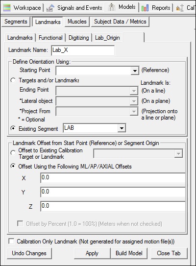
    2. Create Lab_X:


    1. Click Landmarks button


    2. Click Add New Landmark button


    3. Create Landmark: Lab_X

         Landmark Name: Lab_X


         Define Orientation Using:
         Starting Point: Leave Blank
         Existing Segment: LAB


    4. Offset Using the Following ML/AP/AXIAL Offsets:
         X: 0.1    Y: 0.0    Z: 0.0


    5. DO NOT Check: Offset by Percent (1.0 = 100%)


    6. DO NOT Check: Calibration Only Landmark

      vlab_lab_x.jpg

      3. Create Lab_Y:


      1. Click Landmarks button


      2. Click Add New Landmark button


      3. Create Landmark: Lab_Y

           Landmark Name: Lab_Y


           Define Orientation Using:
           Starting Point: Leave Blank
           Existing Segment: LAB


      4. Offset Using the Following ML/AP/AXIAL Offsets:
           X: 0.0    Y: 0.1    Z: 0.0


      5. DO NOT Check: Offset by Percent (1.0 = 100%)


      6. DO NOT Check: Calibration Only Landmark

        vlab_lab_y.jpg

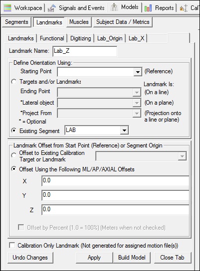
        4. Create Lab_Z:


        1. Click Landmarks button


        2. Click Add New Landmark button


        3. Create Landmark: Lab_Z

             Landmark Name: Lab_Z


             Define Orientation Using:
             Starting Point: Leave Blank
             Existing Segment: LAB


        4. Offset Using the Following ML/AP/AXIAL Offsets:
             X: 0.0    Y: 0.0    Z: 0.1


        5. DO NOT Check: Offset by Percent (1.0 = 100%)


        6. DO NOT Check: Calibration Only Landmark

          vlab_lab_z.jpg


          A subset of 3 of these Landmarks can be used to represent the Segment Coordinate System

          Create the Virtual Laboratory Segment

          To create the Virtual Laboratory segment, switch to the Segment Tab in model builder mode.

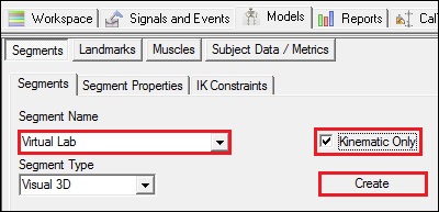
          1. Create the Virtual Lab Segment:

          1. In the Segment Name combo box type Virtual Lab

          2. Check the Kinematic Only Check Box

          3. Select the Create button
          vlab_segmentname.jpg
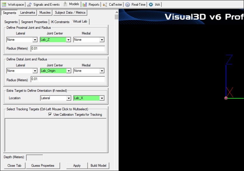
          4. In the Virtual Lab tab, enter these values:

             Define Proximal Joint and Radius

             Lateral: None     Joint: Lab_Z     Medial: None     

             Radius: 0.01

             Define Distal Joint and Radius

             Lateral: None     Joint: Lab_Origin     Medial: None     

             Radius: 0.01

             Extra Target to define Orientation

             Select: Lateral     Lab_X

             Select Tracking Targets:

                Check: Use Calibration Targets for Tracking


          5. Click on Build Model.

          6. Click on Close Tab before proceeding.
          vlab_segmentdefinition.jpg


          Adding a Surface Model


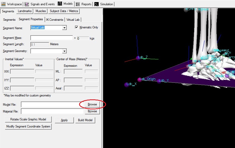
          To add a surface model or graphic switch to the Segment Properties Tab.
          Select Virtual Lab as Segment Name.
          Near the bottom of the dialog Browse for a Model File (.obj or .v3g) of your choosing.


          Select Apply.

          Note: A surface model need not be applied to the virtual lab.
          vlab_segmentproperties.jpg

          Example: Virtual segment aligned with a different principal axis of the laboratory

          The following example will construct a segment coordinate system that is rotated from the laboratory coordinate system.

          An example of a Rotated Virtual Lab can be downloaded here.

          Create 3 Landmarks

          First, create 3 landmarks Lab_Origin, Lab_Other, and Lab_Z. To create these landmarks, go to the Model tab and select the Landmarks tab.


          1. Create Lab_Origin:


          1. Click Landmarks button


          2. Click Add New Landmark button


          3. Create Landmark: Lab_Origin

               Landmark Name: Lab_Origin


               Define Orientation Using:
               Starting Point: Leave Blank
               Existing Segment: LAB


          4. Offset Using the Following ML/AP/AXIAL Offsets:
               X: 0.0    Y: 0.0    Z: 0.0


          5. DO NOT Check: Offset by Percent (1.0 = 100%)


          6. DO NOT Check: Calibration Only Landmark

            vlab_lab_origin.jpg

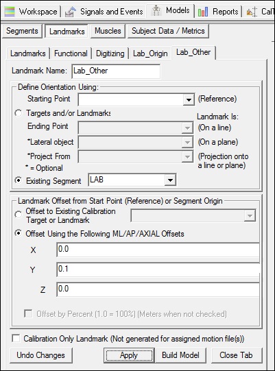
            2. Create Lab_Other:


            1. Click Landmarks button


            2. Click Add New Landmark button


            3. Create Landmark: Lab_Other

                 Landmark Name: Lab_Other


                 Define Orientation Using:
                 Starting Point: Leave Blank
                 Existing Segment: LAB


            4. Offset Using the Following ML/AP/AXIAL Offsets:
                 X: 0.0    Y: 0.1    Z: 0.0


            5. DO NOT Check: Offset by Percent (1.0 = 100%)


            6. DO NOT Check: Calibration Only Landmark

              vlab_lab_other.jpg

              3. Create Lab_Z:


              1. Click Landmarks button


              2. Click Add New Landmark button


              3. Create Landmark: Lab_Z

                   Landmark Name: Lab_Z


                   Define Orientation Using:
                   Starting Point: Leave Blank
                   Existing Segment: LAB


              4. Offset Using the Following ML/AP/AXIAL Offsets:
                   X: 0.0    Y: 0.0    Z: 0.1


              5. DO NOT Check: Offset by Percent (1.0 = 100%)


              6. DO NOT Check: Calibration Only Landmark

                vlab_lab_z.jpg


                Create the Virtual Laboratory Segment

                To create the Virtual Laboratory segment, switch to the Segment Tab in model builder mode and enter the following:

                1. Create the Virtual Lab Segment:

                1. In the Segment Name combo box type Virtual Lab

                2. Check the Kinematic Only Check Box

                3. Select the Create button
                vlab_segmentname.jpg
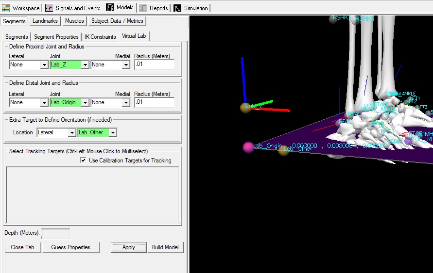
                4. In the Virtual Lab tab, enter these values:

                   Define Proximal Joint and Radius

                   Lateral: None     Joint: Lab_Z     Medial: None     

                   Radius: 0.01

                   Define Distal Joint and Radius

                   Lateral: None     Joint: Lab_Origin     Medial: None     

                   Radius: 0.01

                   Extra Target to define Orientation

                   Select: Lateral     Lab_Other

                   Select Tracking Targets:

                      Check: Use Calibration Targets for Tracking


                5. Click on Build Model.

                6. Click on Close Tab before proceeding.
                vlab_segmentdefinition_ex2labother.jpg


                We have just created a virtual lab that is aligned with a different axis of the lab coordinate system (rotated).

                Example: Creating a virtual laboratory that changes with the direction of walking

                In this example file (Example3.cmo) the subject is walking in the anterior direction in one walking trial and walking in the posterior direction of the laboratory coordinate system (LAB) in the other trial. If the pelvis angle is defined as the pelvis with respect to the laboratory, the data are rotated 180 degrees from the desired angle for one of the trials (see Pelvis Angle wrt Lab). To create a pelvis angle that makes intuitive sense (e.g. in the direction of walking), a virtual lab segment was created. The pelvis angle can then be defined with respect to the virtual lab (see Pelvis Angle wrt Virtual Lab). In Example2.cmo the virtual laboratory was defined statically. But, in this example (Example3.cmo), the Virtual lab is defined relative to the lateral direction of the pelvis segment; the lateral direction is forced to lie along one of the principal axes rather than to float with the pelvis.

                An example of a Virtual Lab which changes with the direction of walking can be downloaded here.


                See Also A virtual lab with 4 possible orientations


                Create 3 Landmarks

                Create 2 landmarks Lab_Origin, Lab_X, and Lab_Z. To create these landmarks, go to the Model tab and select the Landmarks tab.


                1. Create Lab_Origin:


                1. Click Landmarks button


                2. Click Add New Landmark button


                3. Create Landmark: Lab_Origin

                     Landmark Name: Lab_Origin


                     Define Orientation Using:
                     Starting Point: Leave Blank
                     Existing Segment: LAB


                4. Offset Using the Following ML/AP/AXIAL Offsets:
                     X: 0.0    Y: 0.0    Z: 0.0


                5. DO NOT Check: Offset by Percent (1.0 = 100%)


                6. DO NOT Check: Calibration Only Landmark

                  vlab_lab_origin.jpg

                  2. Create Lab_X:


                  1. Click Landmarks button


                  2. Click Add New Landmark button


                  3. Create Landmark: Lab_X

                       Landmark Name: Lab_Other


                       Define Orientation Using:
                       Starting Point: Leave Blank
                       Existing Segment: LAB


                  4. Offset Using the Following ML/AP/AXIAL Offsets:
                       X: 0.1    Y: 0.0    Z: 0.0


                  5. DO NOT Check: Offset by Percent (1.0 = 100%)


                  6. DO NOT Check: Calibration Only Landmark

                    vlab_lab_x.jpg

                    3. Create Lab_Z:


                    1. Click Landmarks button


                    2. Click Add New Landmark button


                    3. Create Landmark: Lab_Z

                         Landmark Name: Lab_Z


                         Define Orientation Using:
                         Starting Point: Leave Blank
                         Existing Segment: LAB


                    4. Offset Using the Following ML/AP/AXIAL Offsets:
                         X: 0.0    Y: 0.0    Z: 0.1


                    5. DO NOT Check: Offset by Percent (1.0 = 100%)


                    6. DO NOT Check: Calibration Only Landmark

                      vlab_lab_z.jpg


                      Create a Landmark from the Pelvis lateral axis projected onto a Laboratory Axis

                      Create a landmark Pelvis_Lateral 10 cm from the Laboratory Origin in the lateral direction of the Pelvis. Create another landmark Pelvis_Lateral_Projected that projects Pelvis_Lateral onto a line formed by the Lab_Origin and Lab_X landmarks. Then create a landmark


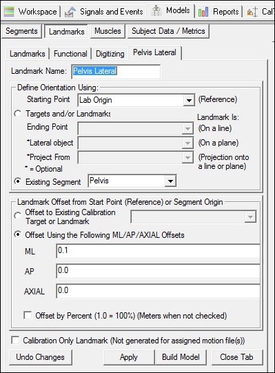
                      1. Create Pelvis_Lateral:


                      1. Click Landmarks button


                      2. Click Add New Landmark button


                      3. Create Landmark: Pelvis_Lateral

                           Landmark Name: Pelvis_Lateral


                           Define Orientation Using:
                           Starting Point: Lab_Origin
                           Existing Segment: Pelvis


                      4. Offset Using the Following ML/AP/AXIAL Offsets:
                           X: 0.1    Y: 0.0    Z: 0.0


                      5. DO NOT Check: Offset by Percent (1.0 = 100%)


                      6. DO NOT Check: Calibration Only Landmark

                        vlab_pelvis_lateral.jpg

                        2. Create Pelvis_Lateral_Projected:


                        1. Click Landmarks button


                        2. Click Add New Landmark button


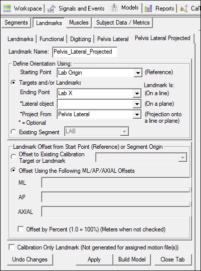
                        3. Create Landmark: Pelvis_Lateral_Projected

                             Landmark Name: Pelvis_Lateral_Projected


                             Define Orientation Using:
                             Starting Point: Lab_Origin
                             Ending Point: Lab_X
                             Project From: Pelvis_Lateral


                        4. DO NOT Check: Offset by Percent (1.0 = 100%)


                        5. DO NOT Check: Calibration Only Landmark

                          vlab_pelvis_lateral_projected.jpg


                          3. Create Lab_Lateral:


                          1. Click Landmarks button


                          2. Click Add New Landmark button


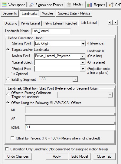
                          3. Create Landmark: Lab_Lateral

                               Landmark Name: Lab_Lateral


                               Define Orientation Using:
                               Starting Point: Lab_Origin
                               Ending Point: Pelvis_Lateral_Projected


                          4. Offset Using the Following AXIAL Offset: 0.1


                          5. DO NOT Check: Offset by Percent (1.0 = 100%)


                          6. DO NOT Check: Calibration Only Landmark

                            vlab_lab_lateral.jpg

                            Create Virtual Laboratory Segment

                            To create the Virtual Laboratory segment, switch to the Segment Tab in model builder mode and enter the following:

                            1. Create the Virtual Lab Segment:

                            1. In the Segment Name combo box type Virtual Lab

                            2. Check the Kinematic Only Check Box

                            3. Select the Create button
                            vlab_segmentname.jpg
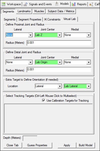
                            4. In the Virtual Lab tab, enter these values:

                               Define Proximal Joint and Radius

                               Lateral: None     Joint: Lab_Z     Medial: None     

                               Radius: 0.01

                               Define Distal Joint and Radius

                               Lateral: None     Joint: Lab_Origin     Medial: None     

                               Radius: 0.01

                               Extra Target to define Orientation

                               Select: Lateral     Lab_Lateral

                               Select Tracking Targets:

                                  Check: Use Calibration Targets for Tracking


                            5. Click on Build Model.

                            6. Click on Close Tab before proceeding.
                            vlab_segmentdefinition_ex3vlabwrtdirection.jpg


                            We have just created a virtual lab that is aligned with the direction of progression of the subject.

                            Example: Virtual Lab Not Aligned with the Lab Axes

                            What if the subject is not walking along the lab axes? What if the subject is walking at a diagonal?

                            To calculate certain measures, such as the trunk angle relative to the lab, the virtual lab should be aligned with the subject's direction of progression. Although there are many methods to do this, some examples can be found here.

                            visual3d/tutorials/modeling/virtual_laboratory.txt · Last modified: 2024/07/17 15:47 by sgranger