Table of Contents
Plug-In Gait Lower Limb Modified
While every effort has been made to ensure the correct implementation of the Plug-In Gait model in Visual3D, some differences may still persist, most likely caused by the different pose estimations used within Nexus and Visual3D.
Introduction
The conventional gait model (CGM) has many variations and can go by many names: Helen Hayes, Vicon Clinical Manager, Newington, and Cleveland Clinic to name a few. We highly recommend reading the Tutorial: Building a Conventional Gait Model prior to going through this tutorial.
Workstation or Nexus users will be familiar with the Plug-In Gait variation as Vicon's implementation of the CGM.
In this tutorial, we describe this implementation of Vicon's Plug-In Gait using Visual3D, with the necessary modifications made for marker placement error specific to this dataset. The original tutorial without modifications can be accessed here.
In some trials, clear errors in marker placement can be identified when viewing the model. Here we make the necessary adaptations to the model to compensate.
Marker Placement Error
The placement of markers during static and dynamic trials can significantly impact the accuracy of the data that is captured. In this static trial markers were only placed on the lateral sides of each leg, with some being nearly co-linear and some incorrectly aligned with anatomical features.
The closer markers are to being placed co-linearly the more difficult it is to define all six degrees of freedom, this can cause error to be amplified leading to an incorrect model.
In this trial, and many others, markers are only placed on the lateral side of each leg. This is done to avoid markers being knocked off during movement trials, however having markers on the lateral and medial side (at least for static trials) helps to improve model accuracy.
The placement of the foot markers, especially the heel, in this trial made it challenging to properly define foot positioning. The Toe_Z landmark was added as a solution to this error.
Modifications Explained
Shank Definition: In this tutorial the RKNE marker was added as the lateral boundary for the right shank definition. This was added to improve alignment of the shank and correct excessive incorrect internal rotation of the tibia that was previously present. In the original tutorial there was a significant difference in alignment between the shank and thigh segments which is not typically present or anatomically possible, this change in definition was done to correct this error.
Toe Landmark and Definition: The R_Toe_Z landmark was introduced to align the anterior axis of the foot with that of the shank and thigh segments (assuming the subject is standing in alignment). It serves as the distal joint center and the posterior foot alignment. In the original model the foot was defined by the heel and toe markers, both of which were incorrectly placed causing clear error in foot positioning.
Load Static Trial
You can download the sample files here. These sample files were generously provided by Vicon (OMG plc, UK).
Load the static trial:
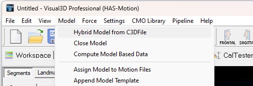
- From the Model menu, select Hybrid Model from C3DFile
- In the Select the calibration file for the new model dialog, select WalkingStaticLowerBody.c3d
- If using a knee alignment device, select Sub01_Static_KAD_01.c3d
- Click Open.
Define Necessary Model Metrics
Create Model Metrics
1. Create Subject Metrics:
- Click Subject Data/Metrics button
- Select the Mass and click the Modify Selected Item button
Name: Mass
Value or Expression: 75
NOTE: This value MUST be changed for each subject
- Select the Height and click the Modify Selected Item button\\ Name: Height
Value or Expression: 1.76
NOTE: This value MUST be changed for each subject
- Click Add New Item button
- Name: MarkerRadius
Value or Expression: 0.005
NOTE: This value MUST reflect the size of the markers used in YOUR lab
- Name: Left_Knee_Width
Value or Expression: 0.105
Create the Right_Knee_Width
NOTE: This value MUST be changed for each subject
- Name: Knee_Width
Value or Expression: (Left_Knee_Width + Right_Knee_Width)/2
- Name: Left_Ankle_Width
Value or Expression: 0.070
Create the Right_Ankle_Width
NOTE: This value MUST be changed for each subject
- Name: Ankle_Width
Value or Expression: (Left_Ankle_Width + Right_Ankle_Width)/2
Pelvis Segment
Pelvis with 4 Targets
For an alternative pelvis definition with 3 targets see the original tutorial.
Pelvis with 4 Targets - Landmarks
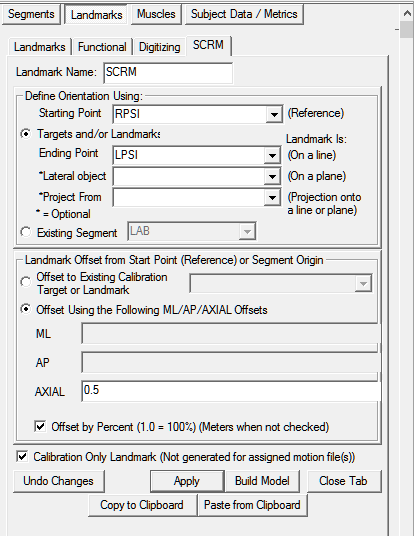
1. Create SCRM:
- Click Landmarks button
- Click Add New Landmark button
- Create Landmark: SCRM
Landmark Name: SCRM
Define Orientation Using:
Starting Point: RPSI
Ending Point: LPSI
Offset Using the Following ML/AP/AXIAL Offsets:
AXIAL: 0.5
Check: Offset by Percent (1.0 = 100%)
Check: Calibration Only Landmark
Pelvis with 4 Targets - Definition
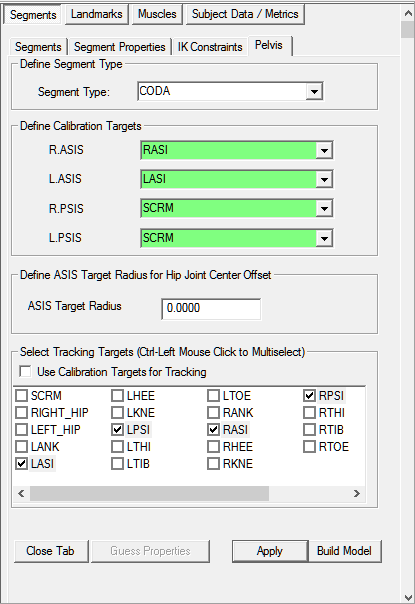
2. Create Pelvis Segment:
- In the Segments tab, select Pelvis in the Segment Name box.
- Select CODA in the Segment Type box.
- Click on the Create Segment button.
- In the Pelvis tab, enter these values:
Define Calibration Targets
R.ASIS: RASI L.ASIS: LASI
R.PSIS: SCRM L.PSIS: SCRM
Define ASIS Target Radius for Hip Joint Center Offset
ASIS Target Radius: MarkerRadius
Select Tracking Targets:
LASI, LPSI, RASI, RPSI
- Click on Build Model.
- Click on Close Tab before proceeding.
Hip Joint Center
The CODA pelvis automatically creates hip joint centers using the Bell and Brand regression equations. The PiG model uses the Davis regression equations.
The directions below walk you through the necessary steps to create the RHJC and LHJC using the Davis regression equations. Please note, some metrics can be manually entered OR target data can be used to estimate these values.
Create Model Metrics for Hip Joint Center
1. Create Subject Metrics:
- Click Subject Data/Metrics button
- Click Add New Item button
- Name: Left_Leg_Length
(A) Value or Expression: 0.940
OR:
(B) Value or Expression: DISTANCE(LASI,LANK)
Create the Right_Leg_Length
NOTE: If you specify an explicit value (ex. 0.940), this value MUST be changed for each subject
- Name: Leg_Length
Value or Expression: (Left_Leg_Length + Right_Leg_Length)/2
- Name: C
Value or Expression: 0.115*Leg_Length - 0.0153
- Name: theta
Value or Expression: 28.4*PI/180.0
- Name: beta
Value or Expression: 18.0*PI/180.0
- Name: Xdis
(A) Value or Expression: 0.750
OR:
(B) Value or Expression: 0.1288*Leg_Length - 0.04856
NOTE: If you specify an explicit value (ex. 0.750), this value MUST be changed for each subject
- Name: HJC_ML
Value or Expression: (C * sin(theta) -0.5 * ASIS_distance)
- Name: HJC_AP
Value or Expression: (-Xdis-MarkerRadius) * cos(beta)+ C * cos(theta) * sin(beta)
- Name: HJC_AX
Value or Expression: (-Xdis-MarkerRadius) * sin(beta)- C * cos(theta) * cos(beta)
Helen Hayes Hip Landmarks
- Click Landmarks button
- Click Add New Landmark button
- Create Landmark: RHIP
Landmark Name: RHIP
Define Orientation Using:
Click Existing Segment: Pelvis
Offset Using the Following ML/AP/AXIAL Offsets:
X: -HJC_ML Y: HJC_AP Z: HJC_AX
Do NOT Check: Offset by Percent (1.0 = 100%)
Do NOT Check: Calibration Only Landmark
2. Create LHIP:
- Click Landmarks button
- Click Add New Landmark button
- Create Landmark: LHIP
Landmark Name: LHIP
Define Orientation Using:
Click Existing Segment: Pelvis
Offset Using the Following ML/AP/AXIAL Offsets:
X: HJC_ML Y: HJC_AP Z: HJC_AX
Do NOT Check: Offset by Percent (1.0 = 100%)
Do NOT Check: Calibration Only Landmark
Thigh Segment
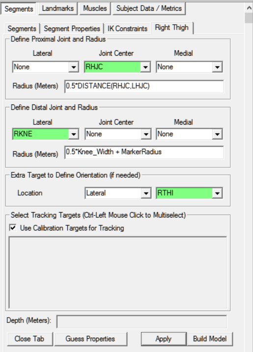
1. Create Right Thigh Segment:
- In the Segments tab, select Right Thigh in the Segment Name box.
- Click on the Create Segment button.
- In the Right Thigh tab, enter these values:
Define Proximal Joint and Radius
Lateral: None Joint: RHJC Medial: None
Radius: 0.5*DISTANCE(RHJC,LHJC)
Define Distal Joint and Radius
Lateral: RKNE Joint: None Medial: None
Radius: 0.5*Knee_Width + MarkerRadius
Extra Target to Define Orientation
Location: Lateral RTHI
Select Tracking Targets:
Check: Use Calibration Targets for Tracking
- Click on Build Model.
- Click on Close Tab before proceeding.
Shank Segment
Shank Landmarks
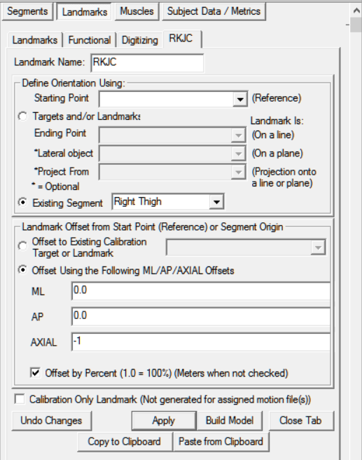
1. Create RKJC:
- Click Landmarks button
- Click Add New Landmark button
- Create Landmark: RKJC
Landmark Name: RKJC
Define Orientation Using:
Click Existing Segment: Right Thigh
Offset Using the Following ML/AP/AXIAL Offsets:
ML: 0.0 AP: 0.0 AXIAL: -1.0
Check: Offset by Percent (1.0 = 100%)
Do NOT Check: Calibration Only Landmark
Shank Definition
1. Create Right Shank Segment:
- In the Segments tab, select Right Shank in the Segment Name box.
- Click on the Create Segment button.
- In the Right Shank tab, enter these values:
Define Proximal Joint and Radius
Lateral: RKNE Joint: RKJC Medial: None
Define Distal Joint and Radius
Lateral: RANK Joint: None Medial: None
Radius: 0.5*Ankle_Width + MarkerRadius
Select Tracking Targets:
Check: Use Calibration Targets for Tracking
- Click on Build Model.
- Click on Close Tab before proceeding.
Foot Segment
Foot Landmarks
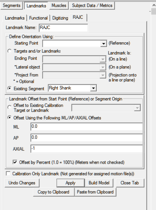
1. Create RAJC:
- Click Landmarks button
- Click Add New Landmark button
- Create Landmark: RAJC
Landmark Name: RAJC
Define Orientation Using:
Click Existing Segment: Right Shank
Offset Using the Following ML/AP/AXIAL Offsets:
ML: 0.0 AP: 0.0 AXIAL: -1.0
Check: Offset by Percent (1.0 = 100%)
Do NOT Check: Calibration Only Landmark
2. Create R_TOE_Z:
- Click Landmarks button
- Click Add New Landmark button
- Create Landmark: R_TOE_Z
Landmark Name: R_TOE_Z
Define Orientation Using:
Click Starting Point and Existing Segment: RTOE and LAB
Offset Using the Following ML/AP/AXIAL Offsets:
ML: 0.0 AP: 0.0 AXIAL: -0.1
Check: Offset by Percent (1.0 = 100%)
Do NOT Check: Calibration Only Landmark
Foot Definition
1. Create Right Foot Segment:
- In the Segments tab, select Right Foot in the Segment Name box.
- Click on the Create Segment button.
- In the Right Foot tab, enter these values:
Define Proximal Joint and Radius
Lateral: None Joint: RAJC Medial: None
Radius: RSK_DISTAL_RADIUS
Define Distal Joint and Radius
Lateral: None Joint: RTOE Medial: None
Radius: RSK_DISTAL_RADIUS
Extra Target to Define Orientation
Location: Posterior R_Toe_Z
Select Tracking Targets:
Select: RHEE, RMT5, and RTOE
- Click on Build Model.
- Click on Close Tab before proceeding.
Virtual Foot Segment
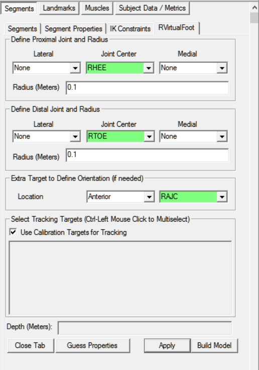
1. Create RVirtualFoot Segment:
- In the Segments tab, type RVirtualFoot in the Segment Name box.
- Check Kinematic Only.
- Click on the Create Segment button.
- In the RVirtualFoot tab, enter these values:
Define Proximal Joint and Radius
Lateral: None Joint: RHEE Medial: None
Radius: 0.1
Define Distal Joint and Radius
Lateral: None Joint: RTOE Medial: None
Radius: 0.1
Extra Target to Define Orientation
Location: Anterior RAJC
Select Tracking Targets:
Check: Use Calibration Targets for Tracking
- Click on Build Model.
- Click on Close Tab before proceeding.
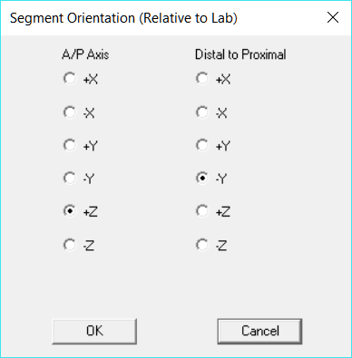
2. Modify the Segment Coordinate System:
- Define the Segment Orientation as:
A/P Axis: +Z
Distal to Proximal: -Y
Left Side Model
To build the left side of the model start by copying and reflecting the appropriate landmarks that were created for the right side. Do the same for the thigh, shank and foot segments.
Impact of Modifications
The images below show the original model, before modifications, compared to the modified model. Significant errors in tibial rotation and foot orientation can be seen in the original that are corrected for in the updated model.
Original:
Modified:
As a result of the modifications made in this tutorial the updated model shows improved alignment between the thigh, shank, and foot segments as well as a more neutral (less supinated) foot position.

