Table of Contents
Instrumented Treadmills
Before going through this tutorial or collecting instrumented treadmill data, you should review the Treadmill page which includes most of the important information you need to know to collect treadmill data in Visual3D.
This tutorial contains basic processing steps that apply to instrumented treadmills, including:
Force Platform Origin Parameter
Instrumented treadmill data from Vicon Nexus is often stored incorrectly in the C3D file. See:
Use Processed Analogs for Ground Reaction Force Calculations
| Specify that ANALOG PROCESSED signals should be used for computing the Ground Reaction Force You want use Processed Targets and Analogs checked, leave Use Processed Forces unchecked. More information about this can be found here. | 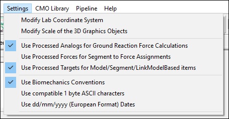 |
Set Minimum Force Threshold
Under the Visual3D Force Menu is an option to set a threshold for force platform/structure data.
| Force → Modify Minimum Force Platform Value… | 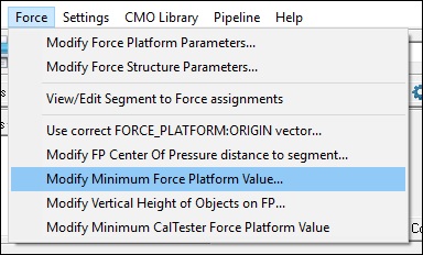 |
| Set the minimum force platform value. Most force platform manufacturers recommend a minimum of 50 N for treadmill data. | 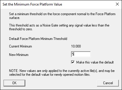 |
If the computed force is less than the minimum force, the force and freemoment are set to zero, the COP is set to DATA_NOT_FOUND. This threshold value is used to remove noise from the force signals. Often for instrumented treadmills this value must be set higher than for overground gait trials.
This value can also be set using the pipeline command Set_Force_Platform_Threshold. This command is listed under the Force category of the pipeline commands.
Filter the ANALOG signals
| 1. Filter the ANALOG data. - Expand the data tree in Signal and Event Processing mode. - With the Right Mouse Button select the ORIGINAL folder under the ANALOG folder. - With the Left Mouse Button select the lowpass option. - Select Done to execute the command. See Signal Processing for an explanation of the default command parameters. | 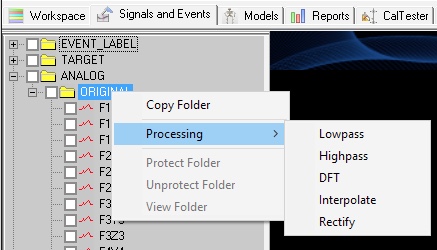 |
| 2. Specify the desired parameters for the Lowpass Filter Command. Example: - Cutoff Frequency: 25 - Samples Reflected: 0 - Samples Extrapolated: 0 - Samples in Buffer: 100 - Bidirectional Passes: 3 | 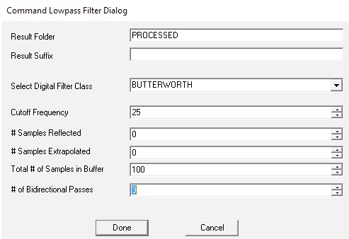 |
| 3. Check that data was filtered: - Note that a PROCESSED folder exists under the ANALOG folder in the data tree. - Expand the PROCESSED folder in the data tree and with the Left Mouse Button select the signal ATFfx. A dialog appears containing 3 tabs. In the Data View tab, note the column headings SUB1, SUB2, etc. These refer to the subframes of the analog signal that arise because the analog sampling rate is higher than the MoCap rate. The Column SUB1 contains the frames of data that are synchronous with the Motion Capture frames. | 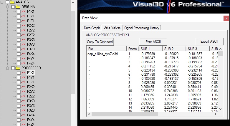 |
| Selecting the History tab displays the processing history of the signal. | 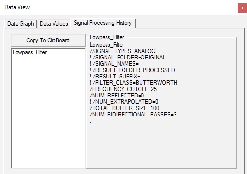 |
4. Hit Recalc to update the workspace No changes will be made to dependent signals until Recalc is hit.
NOTE: These steps can be done using the pipeline using the Lowpass_Filter and Recalc commands.
Analog Signal Baseline Values
For instrumented treadmills, it is critical to set appropriate baselines for the analog signals that compensate for bias in the amplifiers.
For fixed platforms, it is straightforward to a range of frames for which the platform is unloaded. Force Platform Zero Parameters. Note that these are independent of the minimum force threshold and remove the bias on the analog signals when the force platforms are unloaded.
In Visual3D version 6 we have introduced a command FP_Auto_Baseline that automatically determines the appropriate baseline values to remove from each analog signal.
FP_Auto_Baseline ! /FP_NUMBER= ! /AUTO_ZERO=TRUE ! /AUTO_FP_MINIMUM=TRUE ! /USE_REDUCED_FP_MINIMUM_AROUND_FORCE=TRUE ! /REDUCED_FP_MINIMUM=5.0 ; This command does three things:
- Zeros the force signal without having to specify a frame range (AUTO_ZERO)
- Defines the minimum force platform value based on the noise in the signal (AUTO_FP_MINIMUM)
- Looks at the before/after the signal loaded - and finds when the signal crosses the reduced FP minimum to ensure as much of the signal is used as possible (USE_REDUCED_FP_MINIMUM_AROUND_FORCE)
The minimum force platform value is determined by identifying the values of the plate during all the periods where the plate is unloaded. Each force component is used to determine the set of frames containing median values for each component, and a single representative minimum force frame is determined from these values.
Force Assignment
The force assignments to segments should be computed automatically by Visual3D.
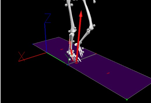
it is vitally important that Force Assignments are checked for validity (e.g. complete stance phase, only one foot in contact with a platform at a time, etc) because the event detection is based on Force Platform Assignments, not on the FORCE signals.
In the figure below the presence of the blue arrow displays the combined force vector from the two platforms.
Examples
This script below is an example of locating the corners using markers, but it's actually recommended to do this using CalTester.
This only needs to be done if your force platforms position changes relative to the motion capture origin - like if you have an inclined treadmill.
| Locating Corners Using Markers |
| Set_Use_Processed_Analog /USE_PROCESSED=TRUE ; ! the minimum force for instrumented treadmill is usually considerable higher than fixed force platforms Set_Force_Platform_Threshold /THRESHOLD=40 /SET_AS_DEFAULT=FALSE ; ! In this example, the analog and target signals are filtered at the same frequency ! This is recommended for Inverse Dynamics Lowpass_Filter /SIGNAL_TYPES=ANALOG ! /SIGNAL_FOLDER=ORIGINAL ! /SIGNAL_NAMES= ! /RESULT_FOLDER=PROCESSED ! /RESULT_SUFFIX= ! /FILTER_CLASS=BUTTERWORTH /FREQUENCY_CUTOFF=20 /NUM_REFLECTED=0 ! /NUM_EXTRAPOLATED=0 /TOTAL_BUFFER_SIZE=1000 /NUM_BIDIRECTIONAL_PASSES=3 ; Lowpass_Filter /SIGNAL_TYPES=TARGET ! /SIGNAL_FOLDER=ORIGINAL ! /SIGNAL_NAMES= ! /RESULT_FOLDER=PROCESSED ! /RESULT_SUFFIX= ! /FILTER_CLASS=BUTTERWORTH /FREQUENCY_CUTOFF=20 ! /NUM_REFLECTED=6 ! /NUM_EXTRAPOLATED=0 ! /TOTAL_BUFFER_SIZE=6 ! /NUM_BIDIRECTIONAL_PASSES=1 ; ! The markers are sitting on top of the corners of the platform, ! so it is necessary to remove the marker radius. ! Instrumented treadmills can be on an angle, so the offset for the ! marker radius should be perpendicular to the platform (not necessarily in a lab axis) Metric_Explicit /RESULT_METRIC_FOLDER=FP /RESULT_METRIC_NAME=MARKER_RADIUS /METRIC_VALUE=0.008 ; ! compute the normal vector to the platform. Evaluate_Expression /EXPRESSION=MEAN(BEST_FIT_PLANE(CURRENT_SIGNAL)) /SIGNAL_TYPES=TARGET+TARGET+TARGET+TARGET /SIGNAL_FOLDER=ORIGINAL+ORIGINAL+ORIGINAL+ORIGINAL /SIGNAL_NAMES=FP1+FP2+FP3+FP4 /RESULT_TYPES=METRIC /RESULT_FOLDERS=FP /RESULT_NAME=FP_NORMAL ! /APPLY_AS_SUFFIX_TO_SIGNAL_NAME=FALSE ; ! Compute the mean value of the markers at the corners ! and remove the marker radius offset. Evaluate_Expression /EXPRESSION=MEAN(TARGET::ORIGINAL::FP1)-METRIC::FP::MARKER_RADIUS*VECTOR(METRIC::FP::FP_NORMAL::X,METRIC::FP::FP_NORMAL::Y,METRIC::FP::FP_NORMAL::Z) ! /SIGNAL_TYPES= ! /SIGNAL_FOLDER=ORIGINAL ! /SIGNAL_NAMES= /RESULT_TYPES=METRIC /RESULT_FOLDERS=FP /RESULT_NAME=C1 ! /APPLY_AS_SUFFIX_TO_SIGNAL_NAME=FALSE ; Evaluate_Expression /EXPRESSION=MEAN(TARGET::ORIGINAL::FP2)-METRIC::FP::MARKER_RADIUS*VECTOR(METRIC::FP::FP_NORMAL::X,METRIC::FP::FP_NORMAL::Y,METRIC::FP::FP_NORMAL::Z) ! /SIGNAL_TYPES= ! /SIGNAL_FOLDER=ORIGINAL ! /SIGNAL_NAMES= /RESULT_TYPES=METRIC /RESULT_FOLDERS=FP /RESULT_NAME=C2 ! /APPLY_AS_SUFFIX_TO_SIGNAL_NAME=FALSE ; Evaluate_Expression /EXPRESSION=MEAN(TARGET::ORIGINAL::FP3)-METRIC::FP::MARKER_RADIUS*VECTOR(METRIC::FP::FP_NORMAL::X,METRIC::FP::FP_NORMAL::Y,METRIC::FP::FP_NORMAL::Z) ! /SIGNAL_TYPES= ! /SIGNAL_FOLDER=ORIGINAL ! /SIGNAL_NAMES= /RESULT_TYPES=METRIC /RESULT_FOLDERS=FP /RESULT_NAME=C3 ! /APPLY_AS_SUFFIX_TO_SIGNAL_NAME=FALSE ; Evaluate_Expression /EXPRESSION=MEAN(TARGET::ORIGINAL::FP4)-METRIC::FP::MARKER_RADIUS*VECTOR(METRIC::FP::FP_NORMAL::X,METRIC::FP::FP_NORMAL::Y,METRIC::FP::FP_NORMAL::Z) ! /SIGNAL_TYPES= ! /SIGNAL_FOLDER=ORIGINAL ! /SIGNAL_NAMES= /RESULT_TYPES=METRIC /RESULT_FOLDERS=FP /RESULT_NAME=C4 ! /APPLY_AS_SUFFIX_TO_SIGNAL_NAME=FALSE ; ! Modify the corner locations Modify_Force_Platform_Parameters /FP_USED=1 /FP_ZERO=0+0 /FP_ZEROS=0+0 /FP_CORNER1=1000*METRIC::FP::C1::X +1000*METRIC::FP::C1::Y +1000*METRIC::FP::C1::Z /FP_CORNER2=1000*METRIC::FP::C2::X +1000*METRIC::FP::C2::Y +1000*METRIC::FP::C2::Z /FP_CORNER3=1000*METRIC::FP::C3::X +1000*METRIC::FP::C3::Y +1000*METRIC::FP::C3::Z /FP_CORNER4=1000*METRIC::FP::C4::X +1000*METRIC::FP::C4::Y +1000*METRIC::FP::C4::Z ; ! Execute the following to compute the baseline bias ! on the analog channels. FP_Auto_Baseline ! /FP_NUMBER= ! /AUTO_ZERO=TRUE /AUTO_FP_MINIMUM=FALSE /USE_REDUCED_FP_MINIMUM_AROUND_FORCE=FALSE ! /REDUCED_FP_MINIMUM=5.0 ; Recalc ; |


