Tutorial RT Biofeedback - Qualisys QTM: Difference between revisions
No edit summary |
m (Text replacement - "www.c-motion.com/download" to "www.has-motion.com/download") |
||
| (2 intermediate revisions by the same user not shown) | |||
| Line 9: | Line 9: | ||
This tutorial describes using the built in real time plugins. | This tutorial describes using the built in real time plugins. | ||
</b> | </b> | ||
| Line 29: | Line 27: | ||
=== Preparing for the Tutorial=== | === Preparing for the Tutorial=== | ||
#Download the file ''[ | #Download the file ''[https://www.has-motion.com/download/RTtutorials/Qualysis/model.zip model.zip]'' | ||
#Save the file where you would normally save motion capture files. | #Save the file where you would normally save motion capture files. | ||
Latest revision as of 11:20, 22 May 2024
| Language: | English • français • italiano • português • español |
|---|
RT Biofeedback is available only in Visual3D Professional.
This tutorial describes using the built in real time plugins.
Introduction
QTM streams out the data it receives as it processes them. Visual3D can save the streamed frames out to a C3D file, or directly capture a static trial from the data streaming in. In other words, QTM must be running and streaming out identified target information. Visual3D can then connect to the active QTM stream to access that data.
QTM is needed in order to stream data to Visual3D so Visual3D cannot replace QTM. Since QTM gives priority to processing the data from the cameras, under higher frame rates they will sacrifice streaming in favor of processing the camera data, thus frames can be lost when streaming at higher data rates.
QTM needs to be running first and activate “Track each frame in 3D” and “Apply the current AIM models” on the RT processing on the Processing page.
To test the RT output you need to be in preview and have an identified subject in the volume or play a file with the “Run Real-Time Processing on File” option.
It is very important that AIM is working properly in Visual3D and identifying markers. If the markers aren't identified in QTM, Visual3D can not process any realtime data.
Preparing for the Tutorial
- Download the file model.zip
- Save the file where you would normally save motion capture files.
These sample Qualysis files were downloaded from C3D.org
Step 1 - Open CMO File
|
1. From the File menu, select Open/Add..., Choose model.cmo
|
|

|
3. Switch to the Models tab to verify bones in picture |
|

Step 2 - Connect to RT stream/Load Emulation
1. Open the Real-Time tab
2. A. To connect to the Qualysis real time stream:
|
|

|
|

2. STOP NOW. This tutorial is just a wiki and cannot connect to your QTM system. So, we will now simulate the RT stream by using a C3D file as input instead. So, disconnect from the QTM system, and use the C3D_Streaming plugin instead. To connect to the C3D stream:
|
|

3. The data is automatically applied to the model
Note: Streaming status in lower left
Step 3 - Compute model based item: RT pipeline
The RT Pipeline is available only in Visual3D Professional
- Open up Model Based Data Computation under the Real-Time Pipeline
- Double click Compute_Model_Based_Data
- Click Edit

- Change the corresponding:
- Data Name: Ankle
- Folder: ORIGINAL
- Model Based Item Properties: JOINT_ANGLE
- Segment: Right Foot
- Reference Segment: Right Shank
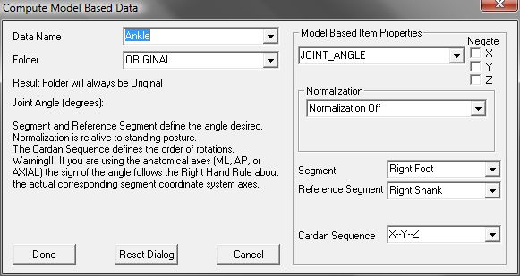
- Click Done


Step 4 - Create Graph
- Click Add in the Real-Time Graphs section, and enter the following:
- Data to: LINK_MODEL_BASED::ORIGINAL::Ankle

- Data to: LINK_MODEL_BASED::ORIGINAL::Ankle
- Click OK

Complete
Your result should show a Real-Time stream that looks like the picture below

Remember to save the Graph and RT Pipeline