CalibrateDSX Overview
| Language: | English • français • italiano • português • español |
|---|
CalibrateDSX prepares the X-ray images and calculates the configuration of the X-ray hardware. It performs three important tasks:
| 1. X-ray Correction |
|---|
|
X-ray images typically suffer from uniformity and distortion errors due to cross-scatter, non-uniform beam intensity, and objects (other than the subject) in the field of view. CalibrateDSX corrects these errors using images taken with an empty field of view (“white” images) and images taken of a uniform grid of holes or beads at known locations (“grid” images). Information on collecting white and grid images can be found here. X-ray images of the calibration object and of the subject are corrected by first pre-processing the white and grid images as follows:
Stacks of grid images are processed via these steps:
Once the white and grid images have been processed, all other X-ray images (calibration object, static subject, motion subject, etc.) can be corrected with these steps:
Note: uniformity correction and distortion correction are both optional. If no white images are specified in the calibration data, uniformity correction will be skipped and the images to be corrected will simply be inverted. Similarly, if no grid images are specified, distortion correction will be skipped. |
| 2. 3D X-ray Configuration |
|---|
|
CalibrateDSX calculates the 3D configuration of the X-ray hardware (the Pose of the X-ray sources and image planes) from images of a rigid calibration object with precisely placed embedded radio opaque beads. Given corrected images of the calibration object, the 3D configuration of the X-ray hardware can be computed. The first step is to digitize the beads of the object in each X-ray view. Identification of the beads can be difficult if there are many of them in the object. A commonly used object contains 64 beads, but only 40 - 50 are visible in each view. To aid identification, uniquely shaped trinkets are sometimes added to the object. CalibrateDSX enables digitizing of the trinkets, or, if there aren’t any, 4 or 5 beads that are easy to identify. From these 4 - 5 trinket/bead locations, the software can calculate where the other beads are expected to be, and locate and identify their centroids on the images. The user can check these automatically digitized beads and manually digitize any that were misidentified. With this step complete, CalibrateDSX now has, for each X-ray view, a set of 2D bead locations in the image plane and a set of 3D bead locations in the lab frame. A simulated annealing algorithm is used for the DLT (direct linear transform) calculations, outputting the following parameters:
|
| 3. Motion Capture Transform |
|---|
|
If traditional motion capture data (e.g., surface markers, inertial sensors) are collected in conjunction with X-ray data, they can be used in X4D to speed the tracking process by determining initial poses of the bones. CalibrateDSX calculates the transform between the X-ray (lab) frame and the frame of the motion capture system (mocap frame) so that the mocap-based bone poses can be converted to the lab frame. It does this using surface markers fixed to the calibration object. The 3D positions of these markers are known in the lab frame, which is embedded in the object. The motion capture system records their 3D positions in the mocap frame, and thus the transform between the lab and mocap frames can be computed. |
Tutorials
How To: Correct X-ray Images and Perform 3D Calibration
How To: Collect Calibration Images
How To: Digitize Points of Interest
The Importance of Image Smoothing and Downsampling
[Video Tutorial on Calibration]
Menus
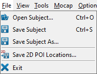
File Menu

- Open Subject... (Ctrl + O)
- loads a subject file.
- Save Subject (Ctrl+ S)
- saves the currently loaded subject to its existing subject file.
- Save Subject As...
- saves the currently loaded subject to a new subject file.
- Save 2D POI Locations...
- saves the current 2D POI locations to text files, one for each view. If names for these files are not already specified in the subject file, you will be prompted to browse for them. Links to these files will then be added to the subject file.
- Exit
- exits the program. The program can also be closed by using the X in the top right corner of the program window.
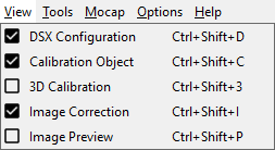
View Menu

- DSX Configuration (Ctrl + Shift + D)
- toggles the appearance of the dockable DSX Configuration widget.
- Calibration Object (Ctrl+ Shift + C)
- toggles the appearance of the dockable Calibration Object widget.
- 3D Calibration (Ctrl+ Shift + 3)
- toggles the appearance of the dockable 3D Calibration widget.
- Image Correction (Ctrl+ Shift + I)
- toggles the appearance of the dockable Image Correction widget.
- Image Preview (Ctrl+ Shift + P)
- toggles the appearance of the dockable Image Preview widget.
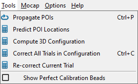
Tools Menu

- Propagate POIs (Ctrl + P)
- propagates all of the digitized POIs in the current object to all of the frames selected in the Tracking slider.
- Predict POI Locations
- predicts the locations of the undigitized POIs from the digitized ones. It works on each view's current frame only, and requires a minimum of four digitized POIs in each view.
- Compute 3D Configuration
- computes the 3D configuration parameters for both views. The source-to-image distance and initial pixel sizes must be specified for both views. At least three POIs on the calibration object must be identified in at least one frame.
- Correct All Trials in Configuration (Ctrl + C)
- corrects the X-ray image files in all of the trials of the current configuration.
- Re-correct Current Trial
- corrects the current trial (whether it's already corrected or not) using the settings in the Image Correction widget.
- Show Perfect Calibration Beads
- toggles the display of projections of the calibration beads onto the X-ray images of the calibration trial. Once the 3D configuration has been computed, rays can be projected from the X-ray sources through each bead until they intersect the images. These intersections, shown as small Xs, represent a "perfect" calibration of the system. That is, if all of the digitized calibration beads (POIs) are coincident with these bead projections, the residuals of the 3D configuration computation will be zero.
Mocap Menu

- Compute DSX/Mocap Transform
- computes the transformation matrix between the X-ray frame defined by the calibration object and the motion capture frame.
- Create Mocap Model (Ctrl + M)
- creates a Visual3D model customized to the subject. A reference trial must be selected and the bones in that trial must have already been tracked for at least one reporting time.
Options Menu
Help Menu

- Help (F1)
- opens the CalibrateDSX wiki page in the default browser.
- About
- displays a dialog with information about CalibrateDSX, including the installed version number. It also contains the Deactivate button, for deactivating your DSX suite license.

