|
|
| (4 intermediate revisions by 2 users not shown) |
| Line 3: |
Line 3: |
| | __TOC__ | | | __TOC__ |
| |} | | |} |
|
| |
| =Introduction=
| |
|
| |
|
| This tutorial explains how to implement the IOR Full Body Model in Visual3D. | | This tutorial explains how to implement the IOR Full Body Model in Visual3D. |
|
| |
|
| The IOR Full Body Model is a combination of the IOR Multi-Segment Trunk<ref name=Leardini>Leardini, A., F. Biagi , A. Merlo, C. Belvedere, and M.G. Benedetti. "Multi-segment trunk kinematics during locomotion and elementary exercises." Clinical Biomechanics 26 (2011): 562-71</ref>, and the IOR Lower Extremity Model<ref name=Cappozzo>Cappozzo, A., F. Catani , U. Della Croce, and A. Leardini. "Position and orientation in space of bones during movement: anatomical frame definition and determination." Clinical Biomechanics 10 (1995): 171-78</ref>. | | The IOR Full Body Model is a combination of the IOR Multi-Segment Trunk<ref name=Leardini>Leardini, A., F. Biagi , A. Merlo, C. Belvedere, and M.G. Benedetti. "Multi-segment trunk kinematics during locomotion and elementary exercises." Clinical Biomechanics 26 (2011): 562-71</ref>, and the IOR Lower Extremity Model<ref name=Cappozzo>Cappozzo, A., F. Catani , U. Della Croce, and A. Leardini. "Position and orientation in space of bones during movement: anatomical frame definition and determination." Clinical Biomechanics 10 (1995): 171-78</ref>. The naming convention used in this tutorial follows Serge Van Sint Jan's convention<ref name=Serge>Serge van Sint Jan "Color Atlas of Skeletal Landmark Definitions: Guidelines for Reproducible Manual and Virtual Palpations" 2007 - Churchill Livingstone</ref>. |
| | |
| The naming convention used in this tutorial follows Serge Van Sint Jan's convention<ref name=Serge>Serge van Sint Jan "Color Atlas of Skeletal Landmark Definitions: Guidelines for Reproducible Manual and Virtual Palpations" 2007 - Churchill Livingstone</ref>. | |
|
| |
|
| ==Downloads== | | ==Downloads== |
|
| |
|
| Sample files may be downloaded [http://www.c-motion.com/download/examples/IORFullBody/IOR_Full_DemoFiles.zip here]. | | Sample files may be downloaded [https://www.has-motion.com/download/examples/IORFullBody/IOR_Full_DemoFiles.zip here]. |
|
| |
|
| The [http://www.c-motion.com/download/examples/IORFullBody/IOR_Full_DemoFiles.zip zip] file contains: | | The [https://www.has-motion.com/download/examples/IORFullBody/IOR_Full_DemoFiles.zip zip] file contains: |
| #C3D files which you can use to follow along with the tutorial | | #C3D files which you can use to follow along with the tutorial |
| #A model template which contains the landmark & segment definitions | | #A model template which contains the landmark & segment definitions |
| Line 467: |
Line 463: |
| |} | | |} |
| | style= "width: 35%" align="right" style="vertical-align:top"| | | | style= "width: 35%" align="right" style="vertical-align:top"| |
| [[File:Lfmshanksegmentorientation.jpg|caption|300px]]
| |
| |} | | |} |
|
| |
|
Latest revision as of 16:04, 22 May 2024
This tutorial explains how to implement the IOR Full Body Model in Visual3D.
The IOR Full Body Model is a combination of the IOR Multi-Segment Trunk[1], and the IOR Lower Extremity Model[2]. The naming convention used in this tutorial follows Serge Van Sint Jan's convention[3].
Downloads
Sample files may be downloaded here.
The zip file contains:
- C3D files which you can use to follow along with the tutorial
- A model template which contains the landmark & segment definitions
- A script which contains the planar & joint angle definitions
- A report template which plots the relevant kinematics (joint angles & planar angles)
- A completed CMO file
Target Placement
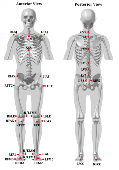
- LCAJ/RCAJ[3] (LA/RA)[1]: Left/Right acromion[3]:p. 45
- SJN[3] (IJ)[1]: Deepest point of incisura jugularis[3]:p. 34
- SXS[3] (PX)[1]: Xiphoid proces, i.e. most caudal point of the sternum[3]:p. 37
- CV7[3] (C7)[1]: Spinous process of the seventh cervical vertebrae[3]:p. 28
- TV2[3] (T2)[1]: Second thoracic vertebrae[3]:p. 29
- TV7[3] (MAI)[1]: Midpoint between the inferior angles of the most caudal points of the two scapulae [3]:p. 61
- LV1, LV3, LV5[3] (L1, L3, L5)[1]: First, third and fifth lumbar vertebrae[3]:p. 29
- LIAS/RIAS[3] (LASIS/RASIS)[1]: Left/Right anterior superior iliac spine[3]:p. 106
- LIPS/RIPS[3] (LPSIS/RPSIS)[1]: Left/Right posterior superior iliac spine[3]:p. 107
- LFTC/RFTC[3] (LGT/RGT)[2]: Most lateral prominence of the greater trochanter[3]:p. 116
- LFLE/RFLE[3] (LLE/RLE)[2]: Most lateral prominence of the lateral femoral epicondyle[3]:p. 122
- LFME/RFME[3] (LME/RME)[2]: Most medial prominence of the medial femoral epicondyle[3]:p. 120
- LFAX/RFAX[3] (LHF/RHF)[2]: Proximal tip of the head of the fibula[3]:p. 154
- LTTC/RTTC[3] (TT/RTT)[2]: Most anterior border of the tibial tuberosity[3]:p. 144
- LFAL/RFAL[3] (LLM/RLM)[2]: Lateral prominence of the lateral malleolus[3]:p. 158
- LTAM/RTAM[3] (LMM/RMM)[2]: Most medial prominence of the medial malleolus[3]:p. 148
- LFCC/RFCC[3] (LCA/RCA)[2]: Aspect of the achilles tendon insertion on the calcaneous[3]:p. 162
- LFM1/RFM1[3] (LFM/RFM)[2]: Dorsal margin of the first metatarsal head[3]:p. 173
- LFM2/RFM2[3] (LSM/RSM)[2]: Dorsal aspect of the second metatarsal head[3]:p. 173
- LFM5/RFM5[3] (LVM/RVM)[2]: Dorsal margin of the fifth metatarsal head[3]:p. 173
Segment Definition
Pelvis
The pelvis segment coordinate system is consistent with the Coda Pelvis, from which the Left and Right Hip Joint centers are automatically created.
|

- LIAS/RIAS[3] (LASIS/RASIS)[1]: Left/Right anterior superior iliac spine[3]:p. 106
- LIPS/RIPS[3] (LPSIS/RPSIS)[1]: Left/Right posterior superior iliac spine[3]:p. 107
|
|
| Pelvis Landmarks
|
|
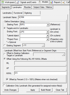
1. Create SCRM:
- Click Landmarks button
- Click Add New Landmark button
- Create Landmark: SCRM
|
Landmark Name: SCRM
Define Orientation Using:
Starting Point: RIPS
Ending Point: LIPS
|
|
- Offset Using the Following ML/AP/AXIAL Offsets:
X: 0.0
Y: 0.0
Z: 0.5
- Check: Offset by Percent (1.0 = 100%)
- Check: Calibration Only Landmark
|
|
|
| Pelvis Definition
|
|
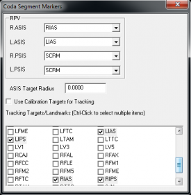
1. Create Pelvis Segment:
- In the Segments tab, select Pelvis in the Segment Name box.
- In Segment Type, select CODA
- Click on the Create Segment button.
- In the Pelvis dialog:
|
Define Calibration Targets
R.ASIS: RIAS
L.ASIS: LIAS
R.PSIS: RIPS
L.PSIS: LIPS
Select Tracking Targets:
LIAS, LIPS, RIAS, RIPS
|
|
- Close Coda Segment Markers dialog box
- Click on Build Model.
- Click on Close Tab before proceeding.
|
|
|
Thorax Segment
This marker set is consistent with the Rizzoli Gait model and the ISB recommendations.
- LCAJ/RCAJ[3] (LA/RA)[1]: Left/Right acromion[3]:p. 45
- SJN[3] (IJ)[1]: Deepest point of incisura jugularis[3]:p. 34
- SXS[3] (PX)[1]: Xiphoid proces, i.e. most caudal point of the sternum[3]:p. 37
- CV7[3] (C7)[1]: Spinous process of the seventh cervical vertebrae[3]:p. 28
- TV2[3] (T2)[1]: Second thoracic vertebrae[3]:p. 29
- TV7[3] (MAI)[1]: Midpoint between the inferior angles of the most caudal points of the two scapulae [3]:p. 61
| Thorax Definition
|
|
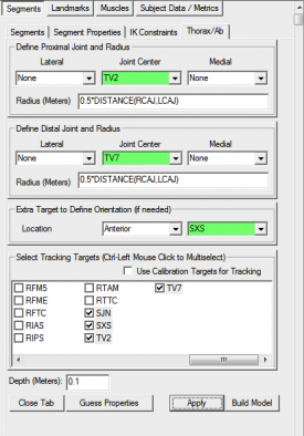
1. Create Thorax/Ab:
- In the Segments tab, select Thorax/Ab in the Segment Name box.
- Click Kinematic Only.
- Click on the Create Segment button.
- In the Thorax/Ab tab, enter these values:
|
Define Proximal Joint and Radius
Lateral: None Joint: TV2 Medial: None
Radius: 0.5*DISTANCE(RCAJ,LCAJ)
Define Distal Joint and Radius
Lateral: None Joint: TV7 Medial: None
Radius: 0.5*DISTANCE(RCAJ,LCAJ)
Extra Target to Define Orientation
Location: Anterior SXS
Select Tracking Targets:
SJN, SXS, TV2, TV7
|
|
- Click on Build Model.
- Click on Close Tab before proceeding.
|
|
|
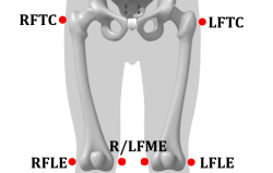
Thigh Segment
The RIGHT_HIP/LEFT_HIP landmarks are used to define the thigh segments. These landmarks are created automatically when the Pelvis segment is defined (so the Pelvis must be defined prior to creating the thigh segments).
|
|
- LFTC/RFTC[3] (LGT/RGT)[2]: Most lateral prominence of the greater trochanter[3]:p. 116
- LFLE/RFLE[3] (LLE/RLE)[2]: Most lateral prominence of the lateral femoral epicondyle[3]:p. 122
- LFME/RFME[3] (LME/RME)[2]: Most medial prominence of the medial femoral epicondyle[3]:p. 120
|
| Thigh Definition
|
|
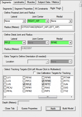
1. Create Right Thigh:
- In the Segments tab, select Right Thigh in the Segment Name box.
- Click on the Create Segment button.
- In the Right Thigh tab, enter these values:
|
Define Proximal Joint and Radius
Lateral: None Joint: RIGHT_HIP Medial: None
Radius: 0.5*DISTANCE(RIGHT_HIP,LEFT_HIP)
Define Distal Joint and Radius
Lateral: RFLE Joint: None Medial: RFME
Select Tracking Targets:
RIGHT_HIP, RFLE, RFME, RFTC
|
|
- Click on Build Model.
- Click on Close Tab before proceeding.
|
|
|
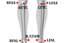
Shank Segment
The segment coordinate system is different from the conventional gait model because the shank segment is defined according to markers located on the tibia and fibula, not the femur as with the Conventional Gait Model.
|
|
- LFAX/RFAX[3] (LHF/RHF)[2]: Proximal tip of the head of the fibula[3]:p. 154
- LTTC/RTTC[3] (TT/RTT)[2]: Most anterior border of the tibial tuberosity[3]:p. 144
- LFAL/RFAL[3] (LLM/RLM)[2]: Lateral prominence of the lateral malleolus[3]:p. 158
- LTAM/RTAM[3] (LMM/RMM)[2]: Most medial prominence of the medial malleolus[3]:p. 148
|
| Shank Landmarks
|
|
1. Create RKNE Joint Center:
- Click Landmarks button
- Click Add New Landmark button
- Create Landmark: RKNE
|
Landmark Name: RKNE
Define Orientation Using:
Starting Point: RFLE
Ending Point: RFME
|
|
- Offset Using the Following AXIAL Offset: 0.5
- Check: Offset by Percent (1.0 = 100%)
- Check: Calibration Only Landmark
|

|
|
2. Create RANK Joint Center:
- Click Landmarks button
- Click Add New Landmark button
- Create Landmark: RANK
|
Landmark Name: RANK
Define Orientation Using:
Starting Point: RFAL
Ending Point: RRAM
|
|
- Offset Using the Following AXIAL Offset: 0.5
- Check: Offset by Percent (1.0 = 100%)
- Check: Calibration Only Landmark
|

|
|
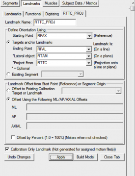
3. Create RTTC_PROJ:
- Click Landmarks button
- Click Add New Landmark button
- Create Landmark: RTTC_PROJ
|
Landmark Name: RTTC_PROJ
Define Orientation Using:
Starting Point: RFAX
Ending Point: RFAL
Lateral Object: RTAM
Project From: RTTC
|
|
- Do NOT Check: Offset by Percent (1.0 = 100%)
- Check: Calibration Only Landmark
|
|
|
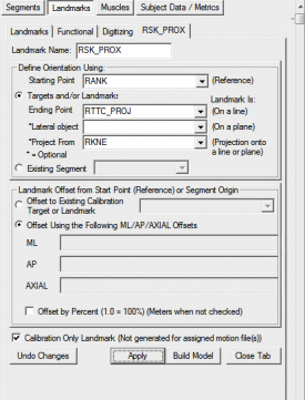
4. Create RSK_PROX:
- Click Landmarks button
- Click Add New Landmark button
- Create Landmark: RSK_PROX
|
Landmark Name: RSK_PROX
Define Orientation Using:
Starting Point: RANK
Ending Point: RTTC_PROJ
Lateral Object: Leave Blank
Project From: RKNE
|
|
- Do NOT Check: Offset by Percent (1.0 = 100%)
- Check: Calibration Only Landmark
|
|
|
| Shank Definition
|
|
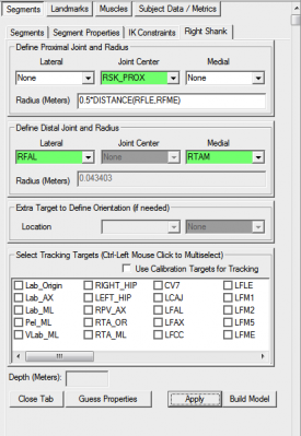
1. Create Right Shank:
- In the Segments tab, select Right Shank in the Segment Name box.
- Click on the Create Segment button.
- In the Right Shank tab, enter these values:
|
Define Proximal Joint and Radius
Lateral: None Joint: RSK_PROX Medial: None
Radius: 0.5*DISTANCE(RFLE,RFME)
Define Distal Joint and Radius
Lateral: RFAL Joint: None Medial: RTAM
Select Tracking Targets:
RFAL, RFAX, RTAM, RTTC
|
|
- Click on Build Model.
- Click on Close Tab before proceeding.
|
|
|
The foot segment coordinate system is consistent with some version of the Conventional Gait Model.
The foot segment is created using the RANK/LANK landmarks which are described in the Shank Landmarks section.
- LFAL/RFAL[3] (LLM/RLM)[2]: Lateral prominence of the lateral malleolus[3]:p. 158
- LTAM/RTAM[3] (LMM/RMM)[2]: Most medial prominence of the medial malleolus[3]:p. 148
- LFCC/RFCC[3] (LCA/RCA)[2]: Aspect of the achilles tendon insertion on the calcaneous[3]:p. 162
- LFM1/RFM1[3] (LFM/RFM)[2]: Dorsal margin of the first metatarsal head[3]:p. 173
- LFM2/RFM2[3] (LSM/RSM)[2]: Dorsal aspect of the second metatarsal head[3]:p. 173
- LFM5/RFM5[3] (LVM/RVM)[2]: Dorsal margin of the fifth metatarsal head[3]:p. 173
| Kinetic Foot Definition
|
|
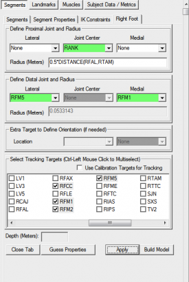
1. Create Right Foot:
- In the Segments tab, select Right Foot in the Segment Name box.
- Click on the Create Segment button.
- In the Right Foot tab, enter these values:
|
Define Proximal Joint and Radius
Lateral: None Joint: RANK Medial: None
Radius: 0.5*DISTANCE(RFAL,RTAM)
Define Distal Joint and Radius
Lateral: RFM5 Joint: None Medial: RFM1
Select Tracking Targets:
RFCC, RFM1, RFM2, RFM5
|
|
- Click on Build Model.
- Click on Close Tab before proceeding.
|
|
|
| Kinematic Foot Landmarks
|
|
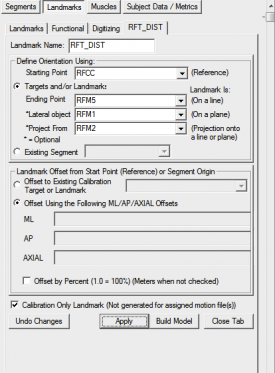
3. Create RFT_DIST:
- Click Landmarks button
- Click Add New Landmark button
- Create Landmark: RFT_DIST
|
Landmark Name: RFT_DIST
Define Orientation Using:
Starting Point: RFCC
Ending Point: RFM5
Lateral Object: RFM1
Project From: RFM2
|
|
- Do NOT Check: Offset by Percent (1.0 = 100%)
- Check: Calibration Only Landmark
|
|
|
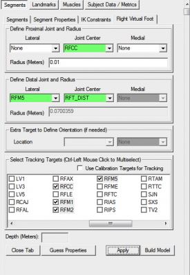
| Kinematic Foot Definition
|
|
1. Create Right Virtual Foot:
- In the Segments tab, type Right Virtual Foot in the Segment Name box.
- Check the Kinematic Only Check Box.
- Click on the Create Segment button.
- In the Right Virtual Foot tab, enter these values:
|
Define Proximal Joint and Radius
Lateral: None Joint: RFCC Medial: None
Radius: 0.1
Define Distal Joint and Radius
Lateral: RFM5 Joint: RFT_DIST Medial: None
Select Tracking Targets:
RFCC, RFM1, RFM2, RFM5
|
|
- Click on Build Model.
- Click on Close Tab before proceeding.
|
|
|
Virtual Lab
| Virtual Lab Landmarks
|
|
1. Create Lab_Origin:
- Click Landmarks button
- Click Add New Landmark button
- Create Landmark: Lab_Origin
|
Landmark Name: Lab_Origin
|
|
- Offset Using the Following ML/AP/AXIAL Offsets:
X: 0.0
Y: 0.0
Z: 0.0
- Do NOT Check: Offset by Percent (1.0 = 100%)
- Do NOT Check: Calibration Only Landmark
|

|
|
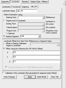
2. Create Lab_AX:
- Click Landmarks button
- Click Add New Landmark button
- Create Landmark: Lab_Origin
- Offset Using the Following ML/AP/AXIAL Offsets:
X: 0.0
Y: 0.0
Z: 0.1
- Do NOT Check: Offset by Percent (1.0 = 100%)
- Do NOT Check: Calibration Only Landmark
|
|
|
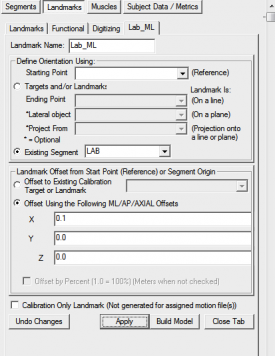
3. Create Lab_ML:
- Click Landmarks button
- Click Add New Landmark button
- Create Landmark: Lab_ML
- Offset Using the Following ML/AP/AXIAL Offsets:
X: 0.1
Y: 0.0
Z: 0.0
- Do NOT Check: Offset by Percent (1.0 = 100%)
- Do NOT Check: Calibration Only Landmark
|
|
|
4. Create Pel_ML:
- Click Landmarks button
- Click Add New Landmark button
- Create Landmark: Pel_ML
|
Landmark Name: Pel_ML
Define Orientation Using:
Starting Point: Lab_Origin
Existing Segment: Pelvis
|
|
- Offset Using the Following ML/AP/AXIAL Offsets:
X: 0.1
Y: 0.0
Z: 0.0
- Do NOT Check: Offset by Percent (1.0 = 100%)
- Do NOT Check: Calibration Only Landmark
|

|
|
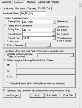
5. Create Pel_ML_Proj:
- Click Landmarks button
- Click Add New Landmark button
- Create Landmark: Pel_ML_Proj
|
Landmark Name: Pel_ML_Proj
Define Orientation Using:
Starting Point: Lab_Origin
Ending Point: Lab_ML
Project Point: Pel_ML
|
|
- Do NOT Check: Offset by Percent (1.0 = 100%)
- Do NOT Check: Calibration Only Landmark
|
|
|
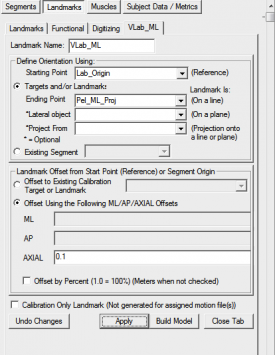
6. Create VLab_ML:
- Click Landmarks button
- Click Add New Landmark button
- Create Landmark: VLab_ML
|
Landmark Name: VLab_ML
Define Orientation Using:
Starting Point: Lab_Origin
Ending Point: Lab_ML
Project Point: Pel_ML_Proj
|
|
- Offset Using the Following ML/AP/AXIAL Offsets:
AXIAL: 0.1
- Do NOT Check: Offset by Percent (1.0 = 100%)
- Do NOT Check: Calibration Only Landmark
|
|
|
| Virtual Lab Definition
|
|
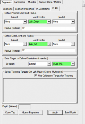
1. Create VLAB:
- In the Segments tab, type VLAB in the Segment Name box.
- Check the Kinematic Only Check Box.
- Click on the Create Segment button.
- In the VLAB tab, enter these values:
|
Define Proximal Joint and Radius
Lateral: None Joint: Lab_Origin Medial: None
Radius: 0.1
Define Distal Joint and Radius
Lateral: None Joint: Lab_AX Medial: None
Radius: 0.1
Extra Target to Define Orientation
Location: Lateral VLab_ML
Select Tracking Targets:
Use Calibration Targets for Tracking
|
|
- Click on Build Model.
- Click on Close Tab before proceeding.
|
|
|
Planar Angles
To calculate the orientation of the trunk segments, planar angles are calculated to determine the orientation of the various segments relative to one another.[1]
To calculate a planar angle, you need to either reference the ORIGINAL or PROCESSED folder when defining a target. If your targets have not been filtered or interpolated, you will not have a processed folder and will need to use the ORIGINAL. However, if you plan to process your target data in any way, you should do this now, prior to creating your planar angles.
|
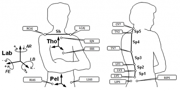
This image was taken from the Multi-Segment trunk paper[1]
|
The following abbreviations are used in naming the planar angles[1]:
- FE Flexion/Extension
- LB Lateral Bending
- AR Axial Rotation
| Spine FE & LB Landmarks
|
|
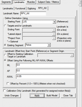
1. Create RPV_AX:
- Click Landmarks button
- Click Add New Landmark button
- Create Landmark: RPV_AX
|
Landmark Name: RPV_AX
Define Orientation Using:
Starting Point: LV5
|
|
- Offset Using the Following ML/AP/AXIAL Offsets:
X: 0.0
Y: 0.0
Z: -0.05
- Do NOT Check: Offset by Percent (1.0 = 100%) (Meters when not checked)
- Do NOT Check: Calibration Only Landmark (Not generated for assigned motion file(s))
|
|
|
FE Planar Angles
Below defines the orientation (flexion/extension) of the adjoining spine segments resolved in the pelvis coordinate system[1] .
NOTE: For the FE Planar Angles, the same definitions for the angles are used for both the left & right side. This means that different sets of signals do not need to be created for the left and right sides (as with the LB and AR planar angles).
| Spine FE Definitions
|
|
1. Create Sp5_Sp4_FE planar angle:
- Define Resulting Signal Name: Sp5_Sp4_FE
- Calculate a 4 point angle between the following targets:
|
1 - TARGET::PROCESSED::TV7
2 - TARGET::PROCESSED::TV2
3 - TARGET::PROCESSED::CV7
4 - TARGET::PROCESSED::TV2
Angle Direction: Left Hand Rule
3D Space: Always 0 to 180 degrees
Projected onto Plane: XY
Note: The reference segment will need to be changed to RPV within the text option.
|
|
|

|
|
2. Create Sp4_Sp3_FE planar angle:
- Define Resulting Signal Name: Sp4_Sp3_FE
- Calculate a 4 point angle between the following targets:
|
1 - TARGET::PROCESSED::LV1
2 - TARGET::PROCESSED::TV7
3 - TARGET::PROCESSED::TV2
4 - TARGET::PROCESSED::TV7
Angle Direction: Left Hand Rule
3D Space: Always 0 to 180 degrees
Projected onto Plane: XY
Note: The reference segment will need to be changed to RPV within the text option.
|
|
|

|
|
3. Create Sp3_Sp2_FE planar angle:
- Define Resulting Signal Name: Sp3_Sp2_FE
- Calculate a 4 point angle between the following targets:
|
1 - TARGET::PROCESSED::LV3
2 - TARGET::PROCESSED::LV1
3 - TARGET::PROCESSED::TV7
4 - TARGET::PROCESSED::LV1
Angle Direction: Left Hand Rule
3D Space: Always 0 to 180 degrees
Projected onto Plane: XY
Note: The reference segment will need to be changed to RPV within the text option.
|
|
|

|
|
4. Create Sp2_Sp1_FE planar angle:
- Define Resulting Signal Name: Sp2_Sp1_FE
- Calculate a 4 point angle between the following targets:
|
1 - TARGET::PROCESSED::LV5
2 - TARGET::PROCESSED::LV3
3 - TARGET::PROCESSED::LV1
4 - TARGET::PROCESSED::LV3
Angle Direction: Left Hand Rule
3D Space: Always 0 to 180 degrees
Projected onto Plane: XY
Note: The reference segment will need to be changed to RPV within the text option.
|
|
|

|
|
5. Create Sp1_Pel_FE planar angle:
- Define Resulting Signal Name: Sp2_Sp1_FE
- Calculate a 4 point angle between the following targets:
|
1 - LANDMARK::ORIGINAL::RPV_AX
2 - TARGET::PROCESSED::LV5
3 - TARGET::PROCESSED::LV3
4 - TARGET::PROCESSED::LV5
Angle Direction: Left Hand Rule
3D Space: Always 0 to 180 degrees
Projected onto Plane: XY
Note: The reference segment will need to be changed to RPV within the text option.
|
|
|

|
|
LB Planar Angles
Below defines the orientation (lateral bending) of the adjoining spine segments resolved in the pelvis coordinate system[1] .
| Spine LB Definitions
|
|
1. Create RSp5_Sp4_LB planar angle:
- Define Resulting Signal Name: RSp5_Sp4_LB
- Calculate a 4 point angle between the following targets:
|
1 - TARGET::PROCESSED::TV7
2 - TARGET::PROCESSED::TV2
3 - TARGET::PROCESSED::CV7
4 - TARGET::PROCESSED::TV2
Angle Direction: Left Hand Rule
3D Space: Always 0 to 180 degrees
Projected onto Plane: YZ
Note: The reference segment will need to be changed to RPV within the text option.
|
|
|

|
|
2. Create LSp5_Sp4_LB planar angle:
- When defining the left signal, use same definitions except set:
|
Angle Direction: Right Hand Rule
|
|
|
3. Create RSp4_Sp3_LB planar angle:
- Define Resulting Signal Name: RSp4_Sp3_LB
- Calculate a 4 point angle between the following targets:
|
1 - TARGET::PROCESSED::LV1
2 - TARGET::PROCESSED::TV7
3 - TARGET::PROCESSED::TV2
4 - TARGET::PROCESSED::TV7
Angle Direction: Left Hand Rule
3D Space: Always 0 to 180 degrees
Projected onto Plane: YZ
Note: The reference segment will need to be changed to RPV within the text option.
|
|
|

|
|
4. Create LSp4_Sp3_LB planar angle:
- When defining the left signal, use same definitions except set:
|
Angle Direction: Right Hand Rule
|
|
|
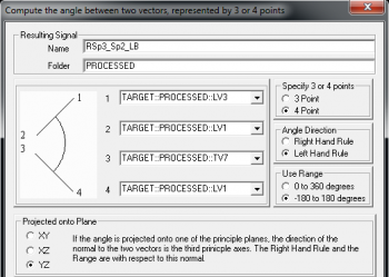
5. Create RSp3_Sp2_LB planar angle:
- Define Resulting Signal Name: RSp3_Sp2_LB
- Calculate a 4 point angle between the following targets:
|
1 - TARGET::PROCESSED::LV3
2 - TARGET::PROCESSED::LV1
3 - TARGET::PROCESSED::TV7
4 - TARGET::PROCESSED::LV1
Angle Direction: Left Hand Rule
3D Space: Always 0 to 180 degrees
Projected onto Plane: YZ
Note: The reference segment will need to be changed to RPV within the text option.
|
|
|
|
|
6. Create LSp3_Sp2_LB planar angle:
- When defining the left signal, use same definitions except set:
|
Angle Direction: Right Hand Rule
|
|
|
7. Create RSp2_Sp1_LB planar angle:
- Define Resulting Signal Name: RSp2_Sp1_LB
- Calculate a 4 point angle between the following targets:
|
1 - TARGET::PROCESSED::LV5
2 - TARGET::PROCESSED::LV3
3 - TARGET::PROCESSED::LV1
4 - TARGET::PROCESSED::LV3
Angle Direction: Left Hand Rule
3D Space: Always 0 to 180 degrees
Projected onto Plane: YZ
Note: The reference segment will need to be changed to RPV within the text option.
|
|
|

|
|
8. Create LSp2_Sp1_LB planar angle:
- When defining the left signal, use same definitions except set:
|
Angle Direction: Right Hand Rule
|
|
|
9. Create RSp1_Pel_LB planar angle:
- Define Resulting Signal Name: RSp2_Sp1_LB
- Calculate a 4 point angle between the following targets:
|
1 - LANDMARK::ORIGINAL::RPV_AX
2 - TARGET::PROCESSED::LV5
3 - TARGET::PROCESSED::LV3
4 - TARGET::PROCESSED::LV5
Angle Direction: Left Hand Rule
3D Space: Always 0 to 180 degrees
Projected onto Plane: YZ
Note: The reference segment will need to be changed to RPV within the text option.
|
|
|

|
|
10. Create LSp1_Pel_LB planar angle:
- When defining the left signal, use same definitions except set:
|
Angle Direction: Right Hand Rule
|
|
|
Shoulder LB
Below defines the orientation of the line between the shoulder targets (LCAJ/RCAJ) relative to the trunk segment[1].
| Shoulder LB & AR Landmarks
|
|
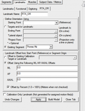
1. Create RTA_OR:
- Click Landmarks button
- Click Add New Landmark button
- Create Landmark: RTA_OR
|
Landmark Name: RTA_OR
Existing Segment: Thorax/Ab
|
|
- Offset Using the Following ML/AP/AXIAL Offsets:
X: 0.0
Y: 0.0
Z: 0.0
- Check: Offset by Percent (1.0 = 100%) (Meters when not checked)
- Do NOT Check: Calibration Only Landmark (Not generated for assigned motion file(s))
|
|
|
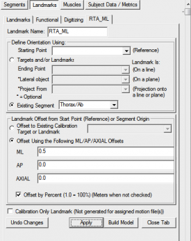
2. Create RTA_ML:
- Click Landmarks button
- Click Add New Landmark button
- Create Landmark: RTA_ML
|
Landmark Name: RTA_ML
Existing Segment: Thorax/Ab
|
|
- Offset Using the Following ML/AP/AXIAL Offsets:
X: 0.5
Y: 0.0
Z: 0.0
- Check: Offset by Percent (1.0 = 100%) (Meters when not checked)
- Do NOT Check: Calibration Only Landmark (Not generated for assigned motion file(s))
|
|
|
| Shoulder LB & AR Definitions
|
|
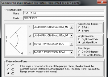
1. Create RSh_Th_LB planar angle:
- Define Resulting Signal Name: RSh_Th_LB
- Calculate a 4 point angle between the following targets:
|
1 - LANDMARK::ORIGINAL::RTA_ML
2 - LANDMARK::ORIGINAL::RTA_OR
3 - TARGET::PROCESSED::LCAJ
4 - TARGET::PROCESSED::RCAJ
Angle Direction: Left Hand Rule
3D Space: Always 0 to 180 degrees
Projected onto Plane: YZ
Note: The reference segment will need to be changed to RTA within the text option.
|
|
|
|
|
2. Create LSh_Th_LB planar angle:
- When defining the left signal, use same definitions except set:
|
Angle Direction: Right Hand Rule
|
|
|
3. Create RSh_Th_AR planar angle:
- Define Resulting Signal Name: RSh_Th_AR
- Calculate a 4 point angle between the following targets:
|
1 - TARGET::PROCESSED::RCAJ
2 - TARGET::PROCESSED::LCAJ
3 - LANDMARK::ORIGINAL::RTA_OR
4 - LANDMARK::ORIGINAL::RTA_ML
Angle Direction: Left Hand Rule
3D Space: Always 0 to 180 degrees
Projected onto Plane: XZ
Note: The reference segment will need to be changed to RTA within the text option.
|
|
|

|
|
2. Create LSh_Th_AR planar angle:
- When defining the left signal, use same definitions except set:
|
Angle Direction: Right Hand Rule
|
|
|
Translation
Below defines the translation of the shoulder targets (LCAJ/RCAJ) in the trunk coordinate system[1] .
| Shoulder Translation Definitions
|
|
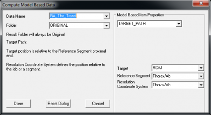
RA_Tho_Transl
|
1. Define RA_Tho_Transl:
- Open the Compute Model Based dialog
- Select TARGET_PATH from drop down list
|
Data Name: RA_Tho_Transl
Target: RCAJ
Reference Segment: Thorax/Ab
Resoluation Coordinate System: Thorax/Ab
|
|
|
|
|
2. Define LA_Tho_Transl:
- When defining the left signal, use same definitions except set:
|
|
Joint Angles
The Tho_Pel and Tho_Lab angles are described here[1], while the lower extremity joint angles were created based on the segment coordinate systems described here[2].
| Joint Angle Definitions
|
|
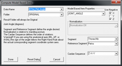
Thorax Pelvis Angle
|
1. Define the RTho_Pel_Angle:
- Open the Compute Model Based dialog
- Select JOINT_ANGLE from drop down list
|
Data Name: RTho_Pel_Angle
Segment: Thorax/Ab
Reference Segment: Pelvis
Cardan Sequence: Z-X-Y
|
|
- Use Negative:
X: TRUE
Y: FALSE
Z: TRUE
|
|
|
2. Define LTho_Pel_Angle:
- When defining the left signal, use same definitions except set:
- Use Negative:
X: FALSE
Y: TRUE
Z: TRUE
|
|
Thorax Lab Angle
|
3. Define the RTho_Lab_Angle:
- Open the Compute Model Based dialog
- Select JOINT_ANGLE from drop down list
|
Data Name: RTho_Lab_Angle
Segment: RThorax/Ab
Reference Segment: VLab
Cardan Sequence: Z-X-Y
|
|
- Use Negative:
X: TRUE
Y: FALSE
Z: TRUE
|

|
|
4. Define LTho_Lab_Angle:
- When defining the left signal, use same definitions except set:
- Use Negative:
X: FALSE
Y: TRUE
Z: TRUE
|
|
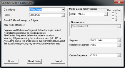
Hip Angle
|
5. Define the RHip_Angle:
- Open the Compute Model Based dialog
- Select JOINT_ANGLE from drop down list
|
Data Name: RHip_Angle
Segment: Right Thigh
Reference Segment: Pelvis
Cardan Sequence: Z-X-Y
|
|
- Use Negative:
X: FALSE
Y: FALSE
Z: FALSE
|
|
|
6. Define LHip_Angle:
- When defining the left signal, use same definitions except set:
|
Segment: Left Thigh
- Use Negative:
X: TRUE
Y: TRUE
Z: FALSE
|
|
Knee Angle
|
6. Define the RKnee_Angle:
- Open the Compute Model Based dialog
- Select JOINT_ANGLE from drop down list
|
Data Name: RKnee_Angle
Segment: Right Shank
Reference Segment: Right Thigh
Cardan Sequence: Z-X-Y
|
|
- Use Negative:
X: FALSE
Y: FALSE
Z: TRUE
|

|
|
7. Define LKnee_Angle:
- When defining the left signal, use same definitions except set:
|
Segment: Left Shank
Reference Segment: Left Thigh
- Use Negative:
X: TRUE
Y: TRUE
Z: TRUE
|
|
Ankle Angle
|
8. Define the RKnee_Angle:
- Open the Compute Model Based dialog
- Select JOINT_ANGLE from drop down list
|
Data Name: RAnkle_Angle
Segment: Right Virtual Foot
Reference Segment: Right Shank
Cardan Sequence: Z-X-Y
|
|
- Use Negative:
X: FALSE
Y: FALSE
Z: FALSE
|

|
|
9. Define LAnkle_Angle:
- When defining the left signal, use same definitions except set:
|
Segment: Left Virtual Foot
Reference Segment: Left Shank
- Use Negative:
X: TRUE
Y: TRUE
Z: FALSE
|
|
|
Detailed tutorial focussing on the IOR Multi-Segment Foot model.
References


