IORgait Troubleshooting: Difference between revisions
No edit summary |
m (Text replacement - "http://www.c-motion.com" to "https://www.c-motion.com") |
||
| Line 119: | Line 119: | ||
2. If your markers are mislabeled return to the software you used for the labeling and correct the error. If the markers are missing completely return to your raw data. Check that these markers have not been accidentally deleted or left unlabeled. If the markers have not been recorded at all these trials are not useable and should be recollected. | 2. If your markers are mislabeled return to the software you used for the labeling and correct the error. If the markers are missing completely return to your raw data. Check that these markers have not been accidentally deleted or left unlabeled. If the markers have not been recorded at all these trials are not useable and should be recollected. | ||
3. If your markers are present return to the problematic sections and check that the segment definitions are correct by double clicking on the segment list to the left of the screen. A complete list of the correct segment definitions can be found [ | 3. If your markers are present return to the problematic sections and check that the segment definitions are correct by double clicking on the segment list to the left of the screen. A complete list of the correct segment definitions can be found [https://www.c-motion.com/v3dwiki/index.php?title=Tutorial:_IOR_Gait_Full-Body_Model here]. | ||
<br>[[Image:SegmentListWithArrow.png]]<br> | <br>[[Image:SegmentListWithArrow.png]]<br> | ||
Latest revision as of 16:21, 20 May 2024
(PRODUCT DISCONTINUED)
| Language: | English • français • italiano • português • español |
|---|
This page is for IORgait troubleshooting. If you have a question or a trouble shooting issue that is not addressed on this page please contact support@c-motion.com with the issue.
Directing IORgait to Visual3D
Locating Visual3D.exe on your computer
If you are having trouble locating where Visual3D is installed you will need to follow the following steps.
1. Confirm that your lab has purchased a copy of Visual3D and that it has been installed on the computer that is running IORgait.
2. Open your windows button at the bottom left corner of the screen.
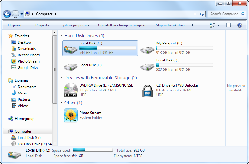
3. Select your hard drive which is typically named the C: drive as it is in this example screen shot.
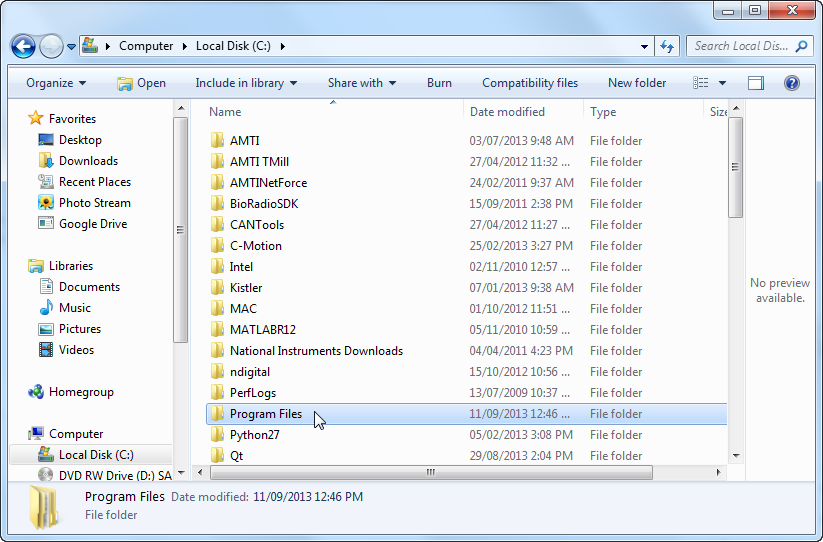
4. Find the file folder called either Program Files or Program Files(x86) and open it. In the example below the folder is called Program Files.
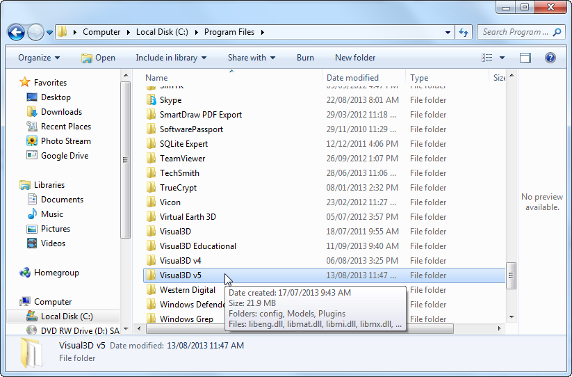
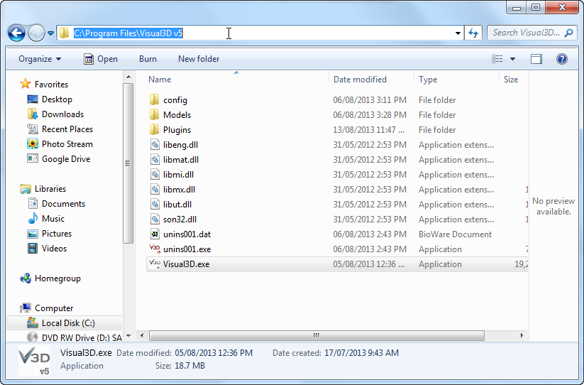
5. Navigate through the list of programs available on your computer until you find the file that has the newest version of Visual3D, open this folder. In the example below the folder is called Visual3D v5.
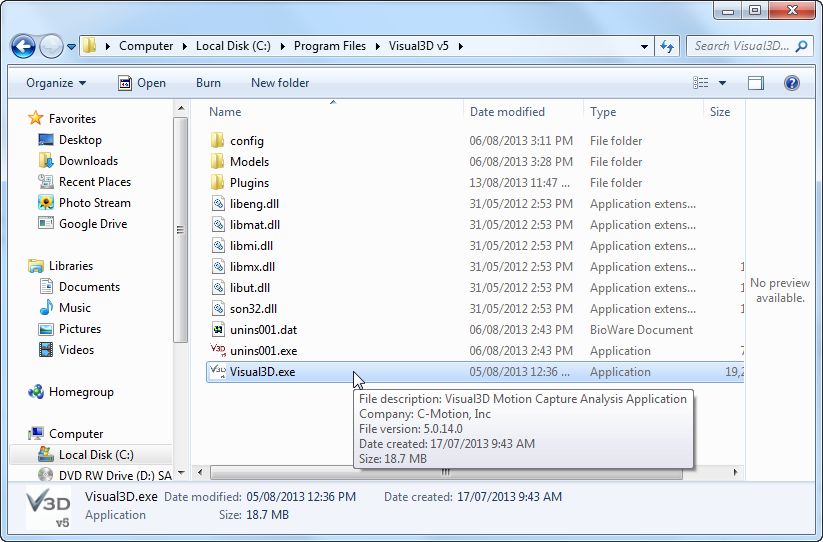
6. Within the Visual3D v5 folder is the Visual3D.exe, this is the application that you have been searching for.
7. You now have two options. You may either return to the Preferences window and use the Browse button to navigate to where you have located the Visual3D.exe application or you can click on the navigation bar at the top of the window as shown in the example below. You can copy and paste the file path (in the example the file path is C:\Program Files\Visual3D v5) into the text box beside Visual3D EXE path in the Preferences window.
8. If you have been unable to complete steps 5 through 7 return to the window seen in step four.
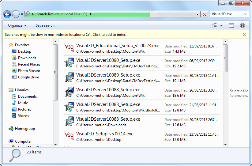
9. Type "Visual3D.exe" into the search function at the top right of the window. This will search and find all files and applications that have Visual3D.exe in their name. If you get no search results then Visual3D is likely not installed on your computer and you will need to buy/install Visual3D. Ideally the search will return a small number of results and you can find the file path by looking at the text beneath the icon. In the example the file path for the first search result is C:\Users\c-motion\Desktop\Moulton\Wiki. Please note that if you have multiple Visual3D versions or C-Motion products you may have a very large list of possibilities, and that narrowing it down may be difficult.
If your model is incorrect
This set of troubleshooting instructions are for if you have reached step 24 of the After the Patient Leaves tutorial and have found errors in the model which was applied.
The three things may indicate there in an error with the model are:
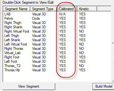
- The segment list on the left hand side of the screen. The Calibration status for all of the segments should read Yes as shown below.
- The view after clicking on the bones button (circled below) and orientate the view screen on the right so that the subject is centered on the screen facing you. The bones should be in the correct position and orientation for a standard human being.
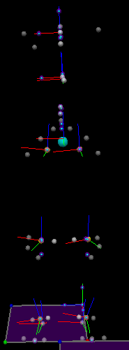
- A visual inspection of the coordinate systems. There should be one for each of the sections that were created, they have three axis, green (x-axis), red (y-axis), and blue(z-axis). When the subject's image is facing you the green axis should be pointing towards you, the red axis should pointing from left to right, and the blue axis should be up and down. A correct model is shown below.
When you know there is a problem with your model go through the following steps for each of the segments that has a problem.
1. Make sure the markers for the segment are present and properly labeled. A diagram and a complete list of markers are shown below.
| Marker Name | Anatomical Acronym | Description | Reference Page |
|---|---|---|---|
| C7 | CV7 | Spinous process of the seventh cervical vertebrae | [1]:p. 28 |
| IJ | SJN | Deepest point of incisura jugularis | [1]:p. 34 |
| L1 | LV1 | First lumbar vertebrae | [1]:p. 29 |
| L3 | LV3 | Third lumbar vertebrae | [1]:p. 29 |
| L5 | LV5 | Fifth lumbar vertebrae | [1]:p. 29 |
| LA/RA | LCAJ/RCAJ | Left/Right acromion | [1]:p. 45 |
| LASIS/RASIS | LIAS/RIAS | Left/Right anterior superior iliac spine | [1]:p. 106 |
| LCA/RCA | LFCC/RFCC | Aspect of the achilles tendon insertion on the calcaneous | [1]:p. 162 |
| LFM/RFM | LFM1/RFM1 | Dorsal margin of the first metatarsal head | [1]:p. 173 |
| LGT/RGT | LFTC/RFTC | Most lateral prominence of the greater trochanter | [1]:p. 116 |
| LHF/RHF | LFAX/RFAX | Proximal tip of the head of the fibula | [1]:p. 154 |
| LLE/RLE | LFLE/RFLE | Most lateral prominence of the lateral femoral epicondyle | [1]:p. 122 |
| LLM/RLM | LFAL/RFAL | Lateral prominence of the lateral malleolus | [1]:p. 158 |
| LME/RME | LFME/RFME | Most medial prominence of the medial femoral epicondyle | [1]:p. 120 |
| LMM/RMM | LTAM/RTAM | Most medial prominence of the medial malleolus | [1]:p. 148 |
| LPSIS/RPSIS | LIPS/RIPS | Left/Right posterior superior iliac spine | [1]:p. 107 |
| LSM/RSM | LFM2/RFM2 | Dorsal aspect of the second metatarsal head | [1]:p. 173 |
| LTT/RTT | LTTC/RTTC | Most anterior border of the tibial tuberosity | [1]:p. 144 |
| LVM/RVM | LFM5/RFM5 | Dorsal margin of the fifth metatarsal head | [1]:p. 173 |
| MAI | approximately TV7 | Midpoint between the inferior angles of the most caudal points of the two scapulae | [1]:p. 61 |
| PX | SXS | Xiphoid proces, i.e. most caudal point of the sternum | [1]:p. 37 |
| T2 | TV2 | Second thoracic vertebrae | [1]:p. 29 |
2. If your markers are mislabeled return to the software you used for the labeling and correct the error. If the markers are missing completely return to your raw data. Check that these markers have not been accidentally deleted or left unlabeled. If the markers have not been recorded at all these trials are not useable and should be recollected.
3. If your markers are present return to the problematic sections and check that the segment definitions are correct by double clicking on the segment list to the left of the screen. A complete list of the correct segment definitions can be found here.

4. If all of the segment definitions are correct and the model still appears to be incorrect then contact support@c-motion.com for further assistance.
If you need to modify Force Assignments
This set of troubleshooting instructions are for if you have reached steps 26 to 29 of the After the Patient Leaves tutorial and have found errors in the force platform contacts.
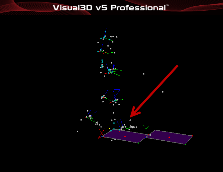
A force platform assignment is correct when it indicates that the correct foot (left or right) is making contact with the force platform. A subjects foot may come into contact with two force platforms at the same time however any force assignment that has two feet on the same platform at the same time is erroneous and should be removed.
1. Make sure that the force assignment is erroneous by carefully inspecting the 3D view on the right of the screen.
2. Click on Force at the top of the screen.
![]()
3. Select View/Edit Segment to Force assignments

4. Select the Force assignment that is incorrect so that it is highlighted in blue and click on the Delete Segment Assignment button.

5. If you are certain that you wish to delete the segment assignment that you have selected click Yes.

6. Repeat steps 4 and 5 as many times as is necessary to remove all the erroneous Force Assignments and then click Ok to exit the View/Modify Force Platform Segment Assignments window.

7. Resume the pipeline and return to the After the Paetient Leaves tutorial.
