Tutorial RT Biofeedback - C3D: Difference between revisions
m (Text replacement - "www.c-motion.com/download" to "www.has-motion.com/download") |
|||
| Line 11: | Line 11: | ||
== Preparing for the Tutorial== | == Preparing for the Tutorial== | ||
#Download the file ''[https://www. | #Download the file ''[https://www.has-motion.com/download/RTtutorials/Qualysis/model.zip model.zip]'' | ||
#Save the file where you would normally save motion capture files. | #Save the file where you would normally save motion capture files. | ||
Latest revision as of 11:20, 22 May 2024
| Language: | English • français • italiano • português • español |
|---|
Purpose
This tutorial shows you how to generate real time feedback from the Visual3D RealTime Tab when streaming a C3D file through Visual3D. The pictures and example in this tutorial are specific to graphing Left Ankle Angles. However, the same principles can be applied to any Link Model Based items.
Steps
Preparing for the Tutorial
- Download the file model.zip
- Save the file where you would normally save motion capture files.
These sample Qualysis files were downloaded from C3D.org
Step 1 - Open CMO File
|
1. From the File menu, select Open/Add..., Choose model.cmo
|
|

|
3. Switch to the Models tab to verify bones in picture |
|

Step 2 - Connect to RT stream/Load Emulation
1. Open the Real-Time tab
| 2.a. To connect to the C3D stream using the Builtin RT plugin: (more....) | ||
|---|---|---|
|

| 2.b. To connect to the C3D stream using the External RT plugin: (more....) | ||
|---|---|---|
|

3. The data is automatically applied to the model
Note: Streaming status in lower left
Step 3 - Compute model based item: RT pipeline
- Open up Model Based Data Computation under the Real-Time Pipeline
- Double click Compute_Model_Based_Data
- Click Edit

- Change the corresponding:
- Data Name: Ankle
- Folder: ORIGINAL
- Model Based Item Properties: JOINT_ANGLE
- Segment: Right Foot
- Reference Segment: Right Shank
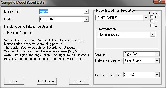
- Click Done


Step 4 - Create Graph
- Click Add in the Real-Time Graphs section, and enter the following:
- Data to: LINK_MODEL_BASED::ORIGINAL::Ankle

- Data to: LINK_MODEL_BASED::ORIGINAL::Ankle
- Click OK

Complete
Your result should show a Real-Time stream that looks like the picture below

Remember to save the Graph and RT Pipeline