Compute Distance Map
| Language: | English • français • italiano • português • español |
|---|
UNDER CONSTRUCTION!!!!!!!!!!!!!!!!
Compute Distance Map
This command will color a region of interest (ROI) on an OBJ file created from DSX with a distance map and calculate the contact point.
Distance maps:
- Each vertex is colored according to its closest distance to the other surface (which can be to a vertex, edge, or triangle of the other surface). Smooth shading is used so that a triangle's color is a linear combination of the colors of its three vertices.
Contact point:
- The overall minimum distance is calculated (_Min)
- The contact path is the weighted minimum distance (_Contact)
Command Output
|
For every Result Name specified, there will be 6 results: |
|

Minimum Distance
|
The minimum distance between the two segments.
|
|

Contact Path
The weighted minimum distance between the two segments.
- Once each face has been assigned a minimum distance, a preliminary contact point is found by calculating a weighted average of all the triangle centers. Each center is weighted by the triangle's area and the square of its distance. The area threshold percentage indicates the percent of the total number of faces on the surface to be included in the calculation. Then the weighted contact point is projected onto the surface of the segment (since the averaged point could be above or below the surface of the segment).
Min Vertex Distances
This is the minimum distance value that is used to color each vertex in the OBJ.
Note: Do not click on this signal and open the data view, Visual3D will not be able to open the data view due to the number of columns.
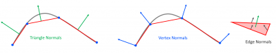
Distance Sign
|
The sign of the minimum distance (positive or negative) is determined by using the face, vertex or edge normals (depending on the test). |
|
Command Dialog
|
Result Signal Information:
Color Map:
Event Sequence:
Regions:
|
|

Drawing the Contact Path
|
For every Result Name specified, there will be 6 results: |
|
|
For every Result Name specified, there will be 6 results: |
|
