RT Plugin NP OptiTrack
| Language: | English • français • italiano • português • español |
|---|
The NaturalPoint™ OptiTrack™ Plugin is used in Visual3D Server™, Capture2D™, and Visual3D RT™, it connects to NaturalPoint™ software.
NOTE: Acquire3D requires NaturalPoint CameraSDK version 1.2.2 (or later) to be installed on your computer.
Plugin Interface
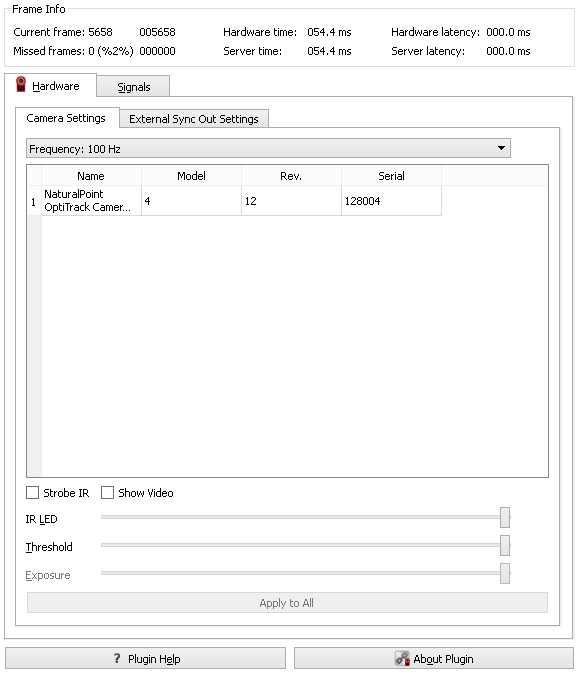
There are two tabs on the left hand side of the screen. These tabs are Hardware, and Signals. Each of these tabs controls a different portion of the plugins functionality. On the right hand side of the window is a 2D view screen which shows a graphical representation of the data the server is receiving from the NP Optitrack hardware.
The "Plugin Help" button leads to this web page should you need to reference this page in the future.
The "About Plugin" button has details on the plugin being used including version, release date, copy right, support contact information and the hardware SDK version.
Frame Info

|
Current frame The current frame number on the top left hand side on the screen (where it currently reads 005658) keeps a count of the current frame which is assigned by the hardware or software system.
Missed frames The missed frames number is on the bottom left (where it currently reads 000000). Whenever there is a gap in frames sent by the hardware of software system a blank frame is inserted. The dropped frames count keeps a record of both the number of frames which are blank.
Hardware time The hardware time number is on the top, in the centre (where it currently reads 054.4). This time stamp is created by the hardware being used and is how long, in milliseconds, the hardware has been running.
Server time The server time number is on the bottom, in the centre (where it currently reads 054.4). This time stamp is created by the server and is how long, in milliseconds, it has been connected to the hardware or software which is streaming to it.
Hardware latency The hardware latency is on the top right hand side (where it currently reads 000.0 ms). This indicated the delay created by the hardware system.
Server latency The hardware latency is on the top right hand side (where it currently reads 000.0 ms). This indicates any delay introduced by the server.
Hardware
Camera Settings
|
Frequency
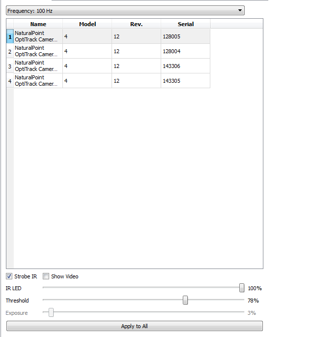
The NP OptiTrack plugin allows you to specify the rate at which you would like to sample the data. The frequency for sampling is measured in Hertz, where 100 Hz is 100 frames per second. Frequency may be set at either 25, 50 or 100 Hz.
Hardware Specifications Table
The Hardware Specifications Table has a list of the hardware units that are connected to Visual3DServer. Not all hardware systems will populates all four columns as not all manufacturers number in four distinct ways on their hardware. The first column "Name" has the make of the hardware (AMTIGen5 for example) and the number of the hardware piece, in case there are more than one type of the same make and model (1, 2, 3 . . .). The second column "Model" lists the hardware model number. The third column "Rev." lists the hardware Revision number which is used by certain hardware system manufacturers and is specific to the piece of hardware. The fourth column "Serial" lists the serial numbers of the hardware pieces which are connected.
Once connected to an OptiTrack system, the infrared (IR) LED level, threshold, and exposure value for each camera can be adjusted. The cameras can also be also have their lights in the strobe function or not, or can be put in video mode. Adjustments are made by selecting a camera with a left mouse click, and dragging the sliders that appear below all the cameras. The default IRED, threshold and exposure values should be suitable for most situations. The basic idea is to reduce as much noise as possible from each camera view using the sliders before doing any capturing. You may want to start by closing blinds and curtains, etc., and removing any unwanted "reflective" objects from your capture volume (extra markers, shinny objects, etc.).
Strobe IR
The OptiTrack™ plugin automatically sets the cameras to strobe their IR lights (the camera's LED ring will strobe on and off quickly instead of emitting infrared (IR) light continuously). Having the IR lights set to strobe as opposed to staying on continuously allows the lights to cool off and increases their life span. The option is given to turn off the strobe setting for cases where the lights will be close to the eyes of some one with photosensitive epilepsy as the strobe light may cause seizures.
Show Video
The cameras can be put into greyscale video mode, by selecting the Show Video checkbox, in order to help position the cameras properly when setting up. It is not recommended that all cameras be placed in video mode at once as this can create a significant time lag in the graphics and slow down the computer. It is also not recommended that the video mode be left on while recording as this slows down the computer and could result in dropped frames.
Intensity
The IR LED level determines intensity of the infrared light each camera emits. IR light illuminates the volume and reflects off of markers. More IR light may be needed in rooms with more natural light.
Internally, the OptiTrack cameras use IRED values 1 through 6 for strobing, with 6 being the brightest strobe setting. Values 6 through 12 are used for non-strobing, with 12 being the brightest setting. The internal values 13 and 14 are meaningless and should be avoided. A value of 15 is meaningful. The OptiTrack™ plugin uses percentages to represent IR LED values. The default IR LED value in the OptiTrack™ plugin is 80%, which corresponds to IR LED value 12, until changed by the user. Avoid slider values that correspond to values 13 and 14.
Threshold
The threshold value determines which pixel intensities are considered part of a tracked centroid. Higher threshold values reduce unwanted reflective noise in the volume. Internally, the OptiTrack cameras use threshold values 0 through 253 inclusive. Beyond 245 noise artifacts occur so the OptiTrack™ plugin only allows values 0 through 245 using percentages (i.e., 100% sets a camera's internal threshold setting to 245). The default threshold value in the OptiTrack™ plugin is 100% until changed by the user.
Exposure
The exposure value alters the sensitivity of the camera allowing more light to enter the lenses as the percentage increases and less as the percentage decreases. The default value is set at 10%. An increase in exposure will make the markers easier to see but will also drastically increase the noise as the cameras pick up other reflections in the environment. Decreasing the exposure will decrease both the visibility of environmental noise and of the markers themselves.
External Sync Out Settings
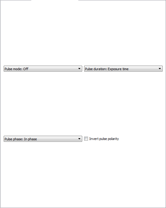
The External Sync Out Settings tells the camera system to output regular pulses in order to allow the camera system to be synchronized with other hardware systems. The setting on this tab allow the user to alter how and when these pulses are emitted.
Pulse Mode
The options for pulse mode are Off, Always on, and On during recording. If you select. Off means that the OptiTrack system will not emit any pulses and thus will not be able to synchronize with other hardware systems. Always on means that the camera system will emit a pulse each time that the camera shutter opens regardless of what is happening elsewhere in the system. The On during recording option is only available in Acquire3D and Capture2D, which are recording systems. It is not present in the Visual3DServer version of the plugin, which does not have a recording function. The On during recording function will send a pulse when the shutter opens only if the computer is recording frames.
Pulse Duration
The options for pulse duration are Exposure time, Pass through, Recording level, and Recording pulse.
Pulse Phase
The options for pulse phase are In phase and Delayed by global offset. If In phase is selected then pulses will be sent when the camera shutters open. If the Delay by global offset is selected then the cameras shutters will open the specified number of milliseconds after the shutter opens.
Invert Pulse Polarity
When the Invert Pulse Polarity is selected the wave of the pulse being sent is inverted. For example if the pulse voltage is 3 volts inverting the polarity will result in a pulse of -3 volts.
External Sync In Settings
The External Sync In Settings tab is currently blank. It will eventually include the ability to accept and read electrical signals from other hardware systems in order to co-ordinate the two.
Signals
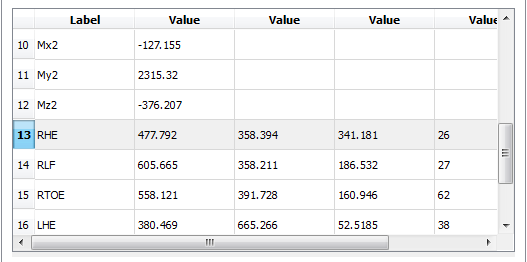
The table in the signals tab holds all of the numerical data from various sources which is being streamed to the program. This data may include, but is not limited to, marker co-ordinates, force data, EMG readings, accelerometer data, etc. The first column entitled "Label" has the number or name which has been assigned to the source of the data. The following four columns are all entitled "Value"; they have the numerical data associated with the source. For markers it is the x, y, and z, coordinates and then the residual. For force data there is only one value associated, which is the magnitude of the force.
|
2D View
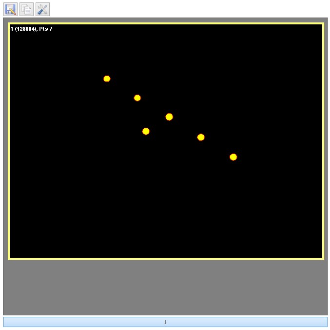
There are three buttons at the top of the 2D view which controls aesthetics and which are discussed in detail below. All of the cameras that are connected have a 2Dview screen. In the sample picture there are four 2D views which show the markers seen by each of the cameras. OptiTrack cameras are unable to independently create a 3D image of the data they collect. The 2D view in the top left corner is circled with yellow indicating that camera is selected. Any changes made to the colors or the camera settings will only be applied to the camera which is selected. More than one camera can be selected at one time. The top left corner of each 2D view has a set of three numbers. The numbers in the example screen shot for the top left 2D view are 1 (128004), Pts 7. They indicate that the camera number is 1, the serial number for camera number one is 128004 and that the camera is seeing 7 separate markers. At the bottom of the 2D view is a row of blue buttons which are numbered. In the example screen shot there are four buttons. These allow you to hide one or more of the 2D views. There must always be at least one 2D camera view present.
Save 2D View
![]()
This button allows you to save what is currently being displayed in the 2D view graphics area. The image can be saved in a number of standard formats, such as .bmp, .ico, .jpeg, .jpg, .pbm, .pgm, .png, .ppm, .tif, .tiff, .wbmp, .xbm, or .xpm. This function is ideal for producing graphics for papers or presentations. Saved images can be edited with 3rd party graphics programs if needed.
Copy 2D View to clipboard
![]()
This button allows you to copy what is currently being displayed in the 2D view graphics area to the clipboard. This allows you to paste the image into any program that supports copy and paste. This is useful for working with presentation or graphics editing software.
2D View Preferences
![]()
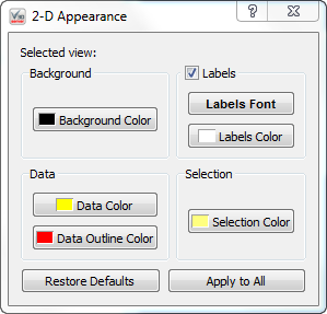
This button allows you to change how the graphics that are presented to you. Changes happen in real time to the camera views that are selected. At the bottom is the "Restore Defaults" button and the "Apply to All" button. The "Restore Defaults" button resets all of the options to their standard setting. The "Apply to All" button applies the changes to all of the camera views which are not currently selected.
|
Background
Background Color - This allows you to change the background color to anyone you chose
Data
Data Color - This allows you to change the color of the data points in the 2D view. Data Outline Color - This allows you to change the color of the data point outlines in the 2D view.
Lables
Labels Checkbox - This allows you to remove the data point labels from the 2D view. Labels Font - This allows you to change the font of the labels at the top left of each camera view. Labels Color - This allows you to change the color of the label to anyone you chose.
Selection
Selection Color - This allows you to change the color of the box that highlights which of the camera views is selected.
