AMASS Tutorial
| Language: | English • français • italiano • português • español |
|---|
Overview
Here is how a new user to AMASS/Capture2D would use the system.
- First, AMASS is installed, and a default data directory for storing motion capture files is created. If an existing L-Frame reference file and marker name file exist, then they are copied to that directory. Finally a project file is created (or modified). The project file will have blank values for the calibration, tracking, and identification sections initially. This is described on the Installation wiki page.
- Once the AMASS Wand (pictured below) arrives in the mail, it is unfolded and the calibration process can start. NOTE: make sure the little black dots on each marker are pointing down, towards the handle. To calibrate a volume, you get all the cameras plugged in and start Capture2D. You then Connect to the cameras and set the duration to 20 seconds (or more if lots of cameras are used). Finally, click Start Recording and wave the wand all around the capture volume - high, low, spinning, waving, and near the floor.

- Save the .cen recording (giving it a meaningful name), and in AMASS, click the Refresh button so that the new file shows up. Then click the Calibrate button. If it doesn't work, collect new data and try again until is does. You simply can't proceed until you have a calibrated volume. There are also troubleshooting pages in the wiki if you have problems. AMASS automatically recognizes the markers on the wand and can linearize the camera lenses, calculates a residual, and calibrates the entire motion capture volume.
- Once the calibration works, click the Apply button in the Calibration report screen.
- Now you can go back to Capture2D and collect subject data for analysis. The tutorial illustrates how to process that data using the track and Identify buttons in AMASS.
Sample Data
Get the [AMASS Sample Files] here.
Getting Started with AMASS
This section provides a brief tutorial of how to use AMASS and the steps necessary to generate 3D data from motion capture data files. It presumes that AMASS is already installed.
The tutorial covers the usual steps followed to process data:
- Set up the Project Files
- Calibrate the 3D volume
- Track the 3D movement of the markers from the multiple camera views
- Identify the markers (e.g. give them meaningful names)
- Write the results to a c3d file.
The following assumes that all the sample files were installed in the: “C:\AMASS_Sample” directory. Note: If the sample files are copied or unzipped elsewhere, then be aware that the Project setup file and the main screen folder selection will need to be modified.
Click on the AMASS program icon in the desktop to start the AMASS shell program.
Note: AMASS starts and loads the last project it was working on. If there was no previous project, or it was moved, then the following screen appears.
Click “Open an Existing Project” and select the sample project file (project.prj) from the files you just installed to begin.
Step 1: Project Control
If the Project name is not Project, click on Open… and navigate to the samples folder. This section duplicates much of the installation information, but goes into more detail about the options.
Make sure the Folder box in the bottom left of the screen points to the sample data.
In the Project Section click on the Edit button and verify that the parameters have the following entries:
Input Tab
This tab set AMASS input data format options. No need to change anything.
- Input system = Capture (multiple input files formats are supported. Capture2D is the program used for NaturalPoint cameras. Other input sources are supported.)
- ViewCen = Checked (to view centroids meaning to actually see the targets/markers)
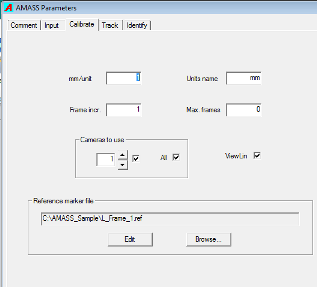
Calibrate Tab
This tab set AMASS volume calibration options.
- Cameras to use = All checked (This option allow you to disable input from specific cameras)
- Reference marker file = C:\AMASS_Sample\L_Frame_1.ref.
Assuming the file location changed, click Browse… and navigate to select the L-Frame file. This file identifies your L-Frame and where the markers are located on it. The sample is for a NaturalPoint frame.
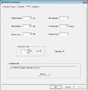
Track Tab
This tab set AMASS target tracking options.
- Calibration file = Delete this entry for the tutorial. If not blank, click Browse… and then Cancel.
This is not critical, since when you create a new calibration file (part of the tutorial) you click an "Apply" button that will overwrite whatever is here.
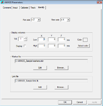
Identify Tab
This tab set AMASS target naming and identification options. No need to change anything unless the file location changed.
- Marker file = marker.mkr. If it is something else, click Browse… and then navigate to select that file.
- Link File = can be blank. It is unused now, but will be needed for the automatic tracking feature (coming soon)
Click OK to close the AMASS Parameters window.
Step 2: Collecting Data
This part assumes you already set up your camera system. Clicking the “Capture” button in AMASS launches the Capture2D program to connect to NaturalPoint cameras and perform a data collection. Use the Advanced button to set non-traditional settings on the cameras. The 3D View tab in newer versions of Capture2D are for force plate data.
In Capture2D, simplistically, you:
- Click the Connect button,
- Set a duration, and then
- Click the Start Recording button.
The result is a file of target centroid data (.cen format) from each camera.
The sample data set provides 3 data collections that would be typical of any biomechanics oriented motion capture effort:
- Calibration_trial.cen = The calibration trial where the wand is waved around the volume to enable calibration. Inadequate wand coverage results in failed calibration, and no further data can be processed. Proper volume calibration is essential to AMASS.
- Static-001.cen = The static trial of the subject, used to build the biomechanical model in Visual3D.
- Movement-001.cen = A movement trial of a subject walking around – not useful for much of any kind on analysis though. It was collected just to test cameras.
Note: If systems other than NaturalPoint are used, a different capture program is needed.
Step 3: Calibrating the Volume
AMASS requires the motion capture volume be properly calibrated before ANY processing can be done. If someone bumps a camera or anything moves or changes, your volume must be re-calibrated.
Using the supplied data files we will illustrate how to calibrate a volume.
Step 1 is to collect data in Capture2D of the wand moving all around the volume. The sample file Calibration_trial.cen is provided so that you see what your own result should look like.
Note: When moving the AMASS Wand around, you want to move it alot - spin it, wave it, get a marker captured in every bit of the lab space as possible and by every camera, and don't forget to wave and spin it right next to the floor too.
Once the data is available, like our sample calibration file, here is how it is processed:
- First, make sure the CEN radio button at the bottom of the AMASS window is selected.
- Highlight the calibration_trial.cen file at the top of the screen. (The project must be set up properly to see this.) Normally you use your own collected data for this.
- Click the Calibrate button in AMASS to create a calibrated volume file. A progress bar will indicate that the calibration/linearization process is taking place, and then the Calibration Report screen will pop up. This resulting calibration file has the .cal extension and contains camera linearization data (to compensate for lens spherical distortions) and volume location.
- Click the APPLY button to tell AMASS to use these results in tracking and identification processes. It will write the file name into the project file.
It is useful to review the data at the top of the Calibration Report. The top part of the window presents an overview of the calibration accuracy and consistency. For example, in this sample we find the point residuals to be 0.594mm, which means that the targets were tracked with sub-millimeter accuracy.
The graphics window indicates the image area of each camera calibrated. The grid also indicates the lens distortions (i.e. linearization map) that were corrected by the calibration. Clicking on a different camera in the camera list box on the right displays the calibration grid for that camera. The reference point information refers to the static markers that are used by the calibration to translate all output to the user’s preferred coordinate system.
You should be able to get considerably better results in your own lab. This sample data was not collected carefully, and the cameras were simply set up on tripods in a random fashion as a system test.
- OPTIONAL step -- To view ANY centroid file (to validate that it looks OK), click the ViewCen button to launch the Centroid Viewer window. You can click each of the cameras views (right panel) and play the data (bottom controls) from each camera in the viewer.
If open, CLOSE the ViewCen window.
Note: Since AMASS automatically recognizes the wand, the L-Frame can also be part of the calibration collection process so that an analysis program like Visual3D will know where the origin of the lab coordinate system is located, and where the lab axis are. You can also put markers on a force plate corner, or make you own L-Frame - just modify the .ref file to let it know where the markers are.
EXTRA Information:
To view the calibration report screen at any time:
- Select the CAL radio button at the bottom
- Highlight the calibration file name
- Click the ViewLin button
Step 4: Tracking Targets
Once the volume has been calibrated, AMASS will then allow the processing of data collected in that volume. For this example, a Static trial and a Movement trial were already collected, and now we can process the data.
The next step is to identify the 3D targets as they move from frame to frame by tracking their individual trajectories and assigning correlated trajectories between camera views to 3D marker segments.
To create the tracking data of the Static trial:
- Click the CEN radio button at the bottom of the screen
- Highlight the Static-001.cen file
- Click the Track button (We skip calibrate button since that is done.)
The result of the tracking process is a 3D marker segments file. This is documented on the wiki, but as a rule of thumb, the more long lines across the screen, the better. Each segment track is given a different color.
This graph shows the number and length of the 3D segments of marker trajectories that were reconstructed from the camera data over the entire data capture time. Each horizontal line indicates a separate segment which is continuous over a number of frames. The marker data at this point are unidentified, i.e. the program does not know which segment belongs to which marker.
- Click Close to exit ViewSeg.
After you close the ViewSeg display the newly created .seg file is saved and automatically selected in the AMASS window. Also, the Identify and ViewLin functions become enabled. We can now proceed to identify the specific markers in the selected .seg file.
Note: This screen can be re-displayed at any time by selecting the SEG radio button, highlighting the seg file, and clicking the ViewSeg button.
Step 5: Identify Targets
Once segment tracking is complete, AMASS enables the Identify button. AMASS should now have the SEG radio button selected and the Static-001.seg file should be highlighted.
- Click the Identify button in AMASS.
The main area shows the 3D marker locations at the first frame. At this point the markers are not identified. That is our next task.
Note: We can manipulate the OpenGL view by dragging the left mouse button to pan and tilt, right mouse button to translate, and both mouse buttons to zoom. Holding the mouse cursor over a marker displays its arbitrarily assigned segment number. You can move to a different frame number by using the slider at the bottom, or auto play by clicking one of the double arrow buttons.
Clicking and holding both mouse buttons, zoom out until all the markers can be seen (as pictured below). The view is from Camera1, but the subject was facing a different camera, and only the lower body had markers. The top group of 4 markers is the pelvis, and the groups at the bottom are the subject’s feet. Thighs, knees, and shanks were also marked.
Double-clicking a marker (or reflection) will "hide" it. Click the UnHide button to show it again.
Now we will identify the markers. There are two methods for assigning marker identifications to the segments. The simplest approach is a one-to-one marking.
- Using the pan, tilt, and zoom capabilities reposition the subject to be facing us in the viewer, and tilt them down a bit to clearly separate the pelvis markers and feet.
- Move the slider to frame 81 – the right knee marker will suddenly appear.
- Click the R-ASIS label in the upper right panel. The markers will also highlight with red circles. Red means that they do not have names associated with them yet.
- Put the mouse over the right ASIS marker #1. Marker numbers appear when the mouse pointer hovers over them.
- Click the marker and it will get assigned. The marker will turn yellow, and the name will appear when the mouse hovers over it. NOTE: double-clicking on the marker will clear an assignment (in case you mislabel one). Beware – double-clicking an unassigned marker hides it (for spurious reflections). The Unhide button on the left can bring it back.
Now, to speed up the process, we can label a group of markers at once.
- Click on the L_ASIS label, and holding down the mouse button, drag the mouse down over the next 3 pelvis marker labels. (Note: Several groups can be created at once this way too.)
- Click on the remaining markers of the pelvis, in descending order in the list.
Notice the bottom of the window. Each marker gets a line across the screen. Gaps in the line indicate drop outs, occlusions, or identification problems. Once the ignition marker identifications are done, we need to play through the file identifying the gaps and fixing any marker errors.
NOTE: Automatic marker identification is possible (and in the next release), but it still requires a setup process and verification step. Automatic identification is a tremendous time saving option, but not a replacement for data validation.
Now we will use the more traditional (and faster) approach that AMASS has for labeling.
- Click in the area to the left of the red bar (the frame indicator) – at the bottom pane of the screen. AMASS will highlight the next unidentified marker like a blue star, and simultaneously highlight the marker names on the right.
- Click the R_THIGH label on the right, and the program will assign the name and automatically move to the next marker. (If it does not move automatically, just click again in to the left of the frame indicator. This happens because when you click there, it moves the frame too, and the “next” markers may already be identified.)
- Label all the markers as shown below. If the program chooses a marker that does not get a name (reflections, etc.) then you may bypass it by either right clicking anywhere in the main viewing area or left clicking to the right of the frame indicator again.
NOTE: You will only see the label names when the mouse is over the marker - we PhotoShopped them in here...
Finally, we need to enhance and validate the result.
Using the slider at the bottom, move through the file looking for unidentified markers and label them. You can also click in the bottom window to jump to frames. We are looking to fill in the gaps in the lines in the bottom viewer (i.e. the continuity display). For example – frame 222 has unidentified markers.
Once you have finished labeling the completed 3D data may now be written to a .c3d file by clicking on the Write C3D button in the left margin.
Save the identifications you have done by writing them back into the seg file by clicking the Save ID’s button on the right. WARNING!! All of the label identifications will be LOST if you do not save them. However, it is the c3d file that needs them more than the seg file. Chances are you will not ever need to relabel a file once written to c3d format.
Summary
That finishes the tutorial. Once a volume is calibrated, markers can be tracked and identified, and then the result saved in c3d format for later analysis.
The Movement-001.seg file has some marker identifications saved already. This file is provided as a sample of any movement data where marker segments are not constant. It is left as an exercise for the user to finish the labeling and write a c3d file.
The next version of AMASS will have the automatic tracking feature enabled. To use that feature, the markers will need to be linked together in either a mesh or as a string of markers (or combination of both). The marker linkages can be saved and re-used as a template, just like the files with marker names.
Good luck!
C-Motion, Inc.


