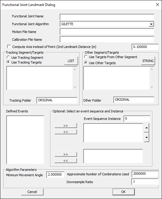
Add Functional Joint Landmark
| Language: | English • français • italiano • português • español |
|---|
This is a legacy command in Visual3D. Visual3D version 4.0 has a new interface for functional joints, and new way of specifying a functional joint landmark as part of the model template. This command should continue to work as originally implemented but it is recommended that you adopt the current approach
This command is based on:
Schwartz MH, Rozumalski A (2005) A new method for estimating joint parameters from motion data. Journal of Biomechanics, 38, 107-116

Add_Functional_Joint_Landmark
| /LANDMARK_NAME= | The name of the landmark to be created. |
| /CALIBRATION_FILE= | The name of the hybrid model. Use the full pathname. |
| /TRACKING_SEGMENT_NAME= | The joint landmark is created relative to an existing segment. For example, for the hip joint center, the pelvis is used. |
| /TRACKING_TYPES= | The types of reference markers used for defining the landmark. |
| /TRACKING_NAMES= | The names of reference markers used for defining the landmark |
| /TRACKING_FOLDER= | The folder containing the tracking markers |
| /OTHER_SEGMENT_NAME= | The name of the other segment (e.g. the landmark does not refer to this segment |
| /SIGNAL_TYPES= | The types of signals used for the tracking markers. |
| /SIGNAL_NAMES= | The names of signals used for the tracking markers. Any number of tracking markers may be used. |
| /SIGNAL_FOLDER= | The folders for signals used for the tracking markers. |
| /MOTION_FILE= | The full pathname of the motion file used. This command allows only one movement file to be used. The user should make sure that a full range of motion about all axes is contained in one file. |
| /EVENT_START= | The start frame for the range of data to be used. |
| /EVENT_STOP= | The Stop frame for the range of frames of data to use. |
| /COMPUTE_SECOND_LANDMARK_ON_AXIS= | TRUE= compute a second landmark that lies on an axis (used for computing a joint axis) |
| /SECOND_LANDMARK_DISTANCE=0.1 | The location of the second landmark relative to the joint center |
| /MINIMUM_HELICAL_ROTATION_ACCEPTED= | Any combination of three frames for which the helical rotation angle is less than 5 degrees are rejected |
| /CREATE_100_REPRESENTATIVE_LANDMARKS= | a random selection of the intermediate Centers of Rotation will be saved as Landmarks. |
| /APPROXIMATE_NUMBER_OF_COMBINATIONS_USED= | If there are a large number of frames of data, the possible combinations of 3 frames becomes very big. The can specify an estimate of the number of combination used (these are selected randomly from the total number of combinations) |
| /SEARCH_WINDOW= | Only Centers of Rotation within the search radius are used for the mean value. |
| /RATE_OF_VOLUME_REDUCTION= | The rate at which the domain of possible solutions is reduced. |
| /NUMBER_OF_ITERATIONS_REDUCING_RADIUS= | The number of times the radius is reduced. At each iteration the cell containing the most crossings is used as the center for the next iteration. |
| /MINIMUM_NUMBER_OF_VALUES_IN_RADIUS= | When the number of landmarks within the current radius falls below this number, the mean value is determined from these markers. |
This command was changed for Visual3D Version 3.83 to allow the specification of REFERENCE MARKERS instead of REFERENCE SEGMENT.
- If a Reference Segment is specified, the landmark will be created relative to that segment.
- If no Reference Segment is specified, the landmark will be created relative to the first three REFERENCE MARKERS (e.g. a Technical Coordinate System will be created from these markers). If more than 3 REFERENCE MARKERS are specified, Visual3D will use all REFERENCE MARKERS to track the Technical Coordinate System.
NOTES
The motion trials being used to identify the functional joint landmark must be assigned to the static calibration trial.
If TRACKING_SEGMENT_NAME is specified, TRACKING_TYPES, TRACKING_NAMES, TRACKING_FOLDER are ignored and can be left blank. The landmark will be created relative to the Tracking Segment.
If TRACKING_SEGMENT_NAME is blank, TRACKING_TYPES, TRACKING_NAMES, TRACKING_FOLDER must be specified. The landmark will be created relative to 3 of the Tracking markers. The first two marker will be selected from the list of tracking markers so that these markers are the maximum distance apart. The third marker will be the maximum distance from a line between the other two.
If OTHER_SEGMENT_NAME is specified, SIGNAL_TYPES, SIGNAL_NAMES, SIGNAL_FOLDER are ignored and can be left blank.
If OTHER_SEGMENT_NAME is balcn, SIGNAL_TYPES, SIGNAL_NAMES, SIGNAL_FOLDER must be specified.