CalTesterPlus Tutorials Report
| Language: | English • français • italiano • português • español |
|---|
Collecting
In order to use the CalTesterPlus program you need a set of properly collected data for each force platform you wish to calibrate. To collect a useful motion trial for the report mode follow the following process.
- Each example motion trial that is downloaded with the CalTesterPlus program meets these criteria.
Dynamic Trials
|
Create Report
Creating a report gives you a written report of your CalTester c3d file. This report can either be saved as a PDF, as a text file, to a data base or printed. You can either complete this tutorial using data you have collected in your own lab following the guide lines above, or by using the sample data that was downloaded when you installed CalTesterPlus. This sample data can be found on the following file path: C:\Program Files\C-Motion\CalTesterPlus\Samples\Tutorial1
1. Add C3D files
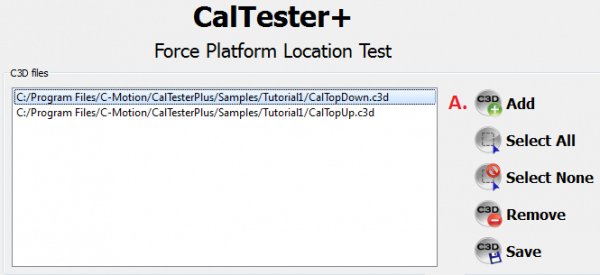
Use the add button at the top right hand side of the screen to load all of the .c3d files that you want to use to create a report from, and select them by highlighting them.
For the sample data we will be using the file entitled "CalTopUp.c3d"
2. Select Report Tab
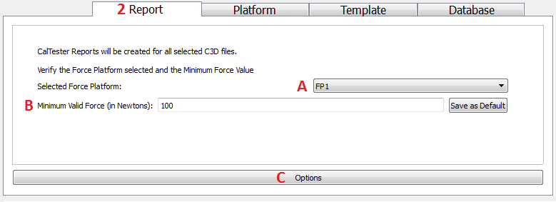
Make sure that you are on the Report tab at the bottom section of the screen.
(A) Check that you have selected FP 1 if you are using the sample data if you are using your own make sure that the force platform number corresponds to the force platform number that the CalTester Rod was applied to.
(B) Check that the Minimum valid force is set to 100 N.
(C) Click on the Options button at the bottom of the screen.
3. Check the CalTester rod labels:
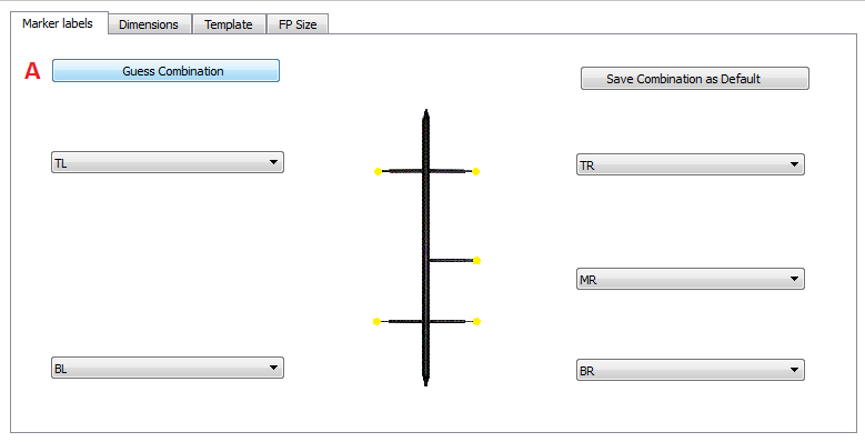
(A) If the CalTester rod is not already labeled click the Guess Combinations button.
(B) Verify that the CalTester Rod has been appropriately labeled. The proper labeling for the sample data is shown below. The Save Combination as Default button can be used if this is a naming convention that you will be reusing.
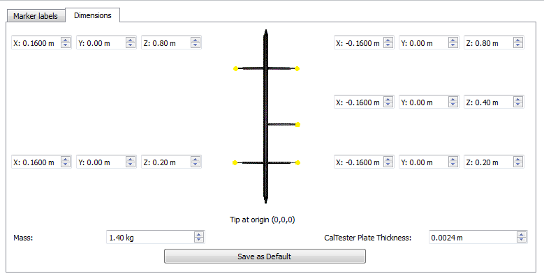
4. Check the dimensions of the CalTester Rod
- If you are using the sample data or the CalTester Rod manufactured by Motion Lab Systems use the values that are specified below.
- If you have made your own rod you will need to enter the correct measurements. See here for more information.
5. Select Go
Click on the Go button at the bottom of the screen.
7. The Report
A new window should appear with the report.
- For details on what each page of the report means see below. Note: If you see a report error see here for an explanation.
Report Metrics
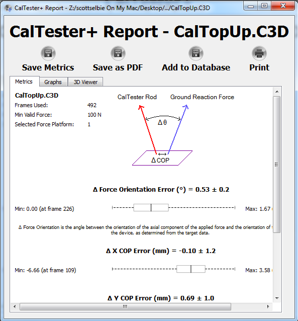
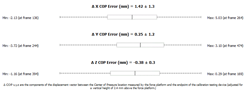
The Metrics tab will show the full report detailing the four variables: the difference in the force vector orientation Delta Force Orientation, expressed as an angle), and the differences in the three coordinates of the CoP location. The report will also detail and show graphically the mean and standard deviation of each variable.
If multiple C3D files were selected from the "C3D files" list box, a report for each file will be created. Each report will be created in a new window (move the top report window to see the report for the next trial).
Report Graphs
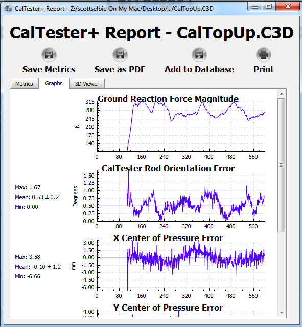
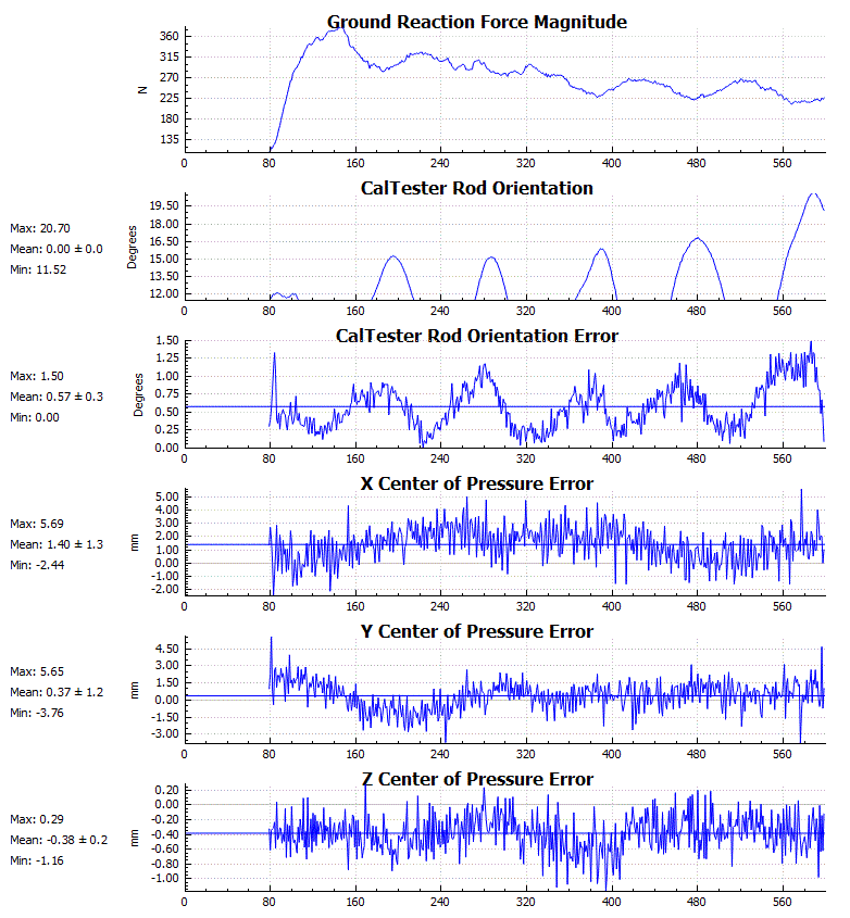
Clicking on the Report Graph tab will allow you to see five graphs:
- The Ground Reaction Force Magnitude graph will show the magnitude of the ground reaction force over time. This is a nice consistency and error check to see if you have reached the 100N force level throughout the rod movement.
- The CalTester Rod Orientation graph shows the rod orientation over time. Min, max, mean and standard deviation will appear to the left and the graph will show the mean line.
- The CalTester Rod Orientation Error graph shows the rod orientation error over time. Min, max, mean and standard deviation will appear to the left and the graph will show the mean line.
- X Center of Pressure Error graph shows the X center of pressure error over time. Min, max, mean and standard deviation will appear to the left and the graph will show the mean line.
- Y Center of Pressure Error graph shows the Y center of pressure error over time. Min, max, mean and standard deviation will appear to the left and the graph will show the mean line.
- Z Center of Pressure Error graph shows the Z center of pressure error over time. Min, max, mean and standard deviation will appear to the left and the graph will show the mean line.
From this view the user can select the range of data to be processed. This will allow the user to eliminate anomalous data from the calibration calculations. To select the range, left click and drag the mouse on the Ground Reaction Force Magnitude graph. A green highlighted section will appear on the graph and all of the graphs will be limited to this range. To return to the original range, left click on the Ground Reaction Force Magnitude graph and the full range will return to all of the graphs.
Report 3DViewer
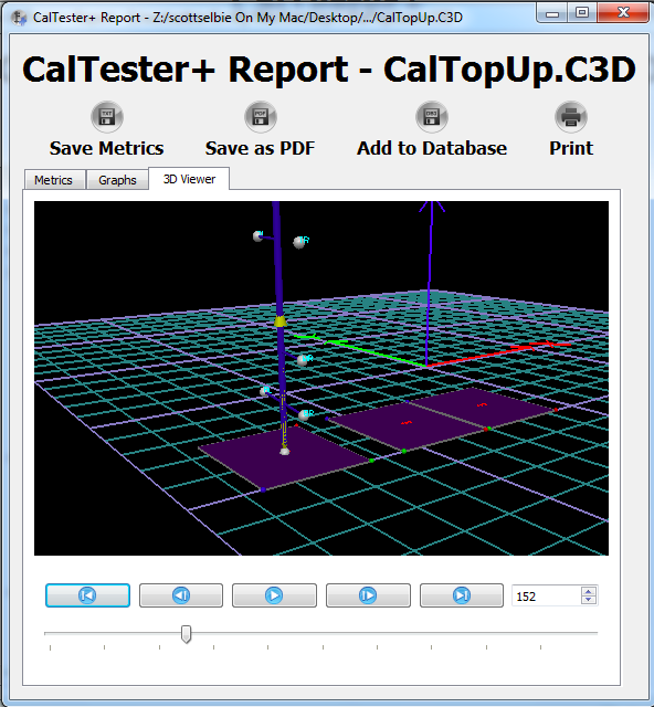
Clicking on the 3D Viewer tab will show the 3D View of the rod data collection session. This session can be reviewed by using the video navigation buttons (play, advance one frame, stop, etc) or by dragging the scroll bar on the bottom. If you wish to go to a specific frame, then enter that into the bottom right hand window. To navigate inside the viewer window use your mouse and right or left mouse button to zoom in and out and rotate the view. Reviewing the session in the 3D Viewer is a great way to see how the force vector orientation lines up with the rod.
Report Export Options
There are several report export options available:
- Save Metrics will export the min, max and mean from the Metrics tab to a text file.
- Save As PDF will save the report as a PDF file.
- Add to Database will export the report to a database.
- Print Report will send the report to your printer in order to be printed.
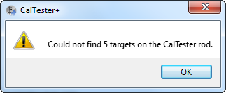
Report Error
If you get the above error message you have loaded a file that contains insufficient data to create a report. In the sample files loaded with the CalTesterProgram (file path C:\Program Files\C-Motion\CalTesterPlus\Samples\TutorialFiles) Trial3.c3d has been created purposely with erroneous data so that you can recreate this error.
Interpreting the Report Results
The Laboratory Calibration Test Report includes the mean, standard deviation, and range (minimum and maximum) of the four report variables. These are provided on graphs and with numerical values.
(1) The number of frames used, minimum valid force on the platform used, and which FP was analyzed are displayed on the upper right hand corner:
(2) The difference in Force Orientation is reported as the angle (in degrees) between the applied force reaction vector (i.e., the ground reaction force minus the weight of the calibration-testing rod) and the orientation of the long axis of the rod, as determined from the target data:
Note: The force orientation variable is calculated from the dot product of this predicted unit vector and the vector along the axis of the rod as determined with the motion capture system.
(3) The differences in CoP x,y,z are the components of the displacement vector between the CoP location measured by the force platform and the endpoint of the calibration-testing rod (adjusted for the specified vertical height above the force platform):
Differences can be due to many different factors, including errors in the force platform configuration (analog scale factors, force platform origin specification), the force platform interface (channel connections and assignments), or the force platform alignment (corner locations, which are used to transform force platform data into the laboratory coordinate system). Differences due to the kinematic system are related to uncorrected camera non-linearities, poor 3D calibration, and target image distortions.
If necessary, the calibration test data can be saved by selecting the desired "Save" item on the toolbar. This allows more detailed examination of the data that went into the Laboratory Calibration Test Report.
If the program detects large differences, additional data collection trials may be helpful in identifying the source(s) of the differences. The additional tests may include separate data collection trials using movement arcs in only one of the vertical planes, or a circular movement arc. Tests in each of the four quadrants of the force platform may also be helpful. The significance of the measured differences is a professional judgment that must be made by each laboratory in light of its specific applications. (Keep in mind that the measurement resolution of laboratory systems will limit how small one can reasonably expect the differences to be.) Also, the CalTester technique is sensitive to a great many parameters, but the process of identifying the parameter(s) that most contributes to differences will likely require a thorough understanding of the measurement systems by the user.
If the program detects an inconsistent value for the location of the origin of the force platform, it assumes that the data file was generated from a VICON system and indicates that beside the filename on the report.
The magnitude of the force vector and the error signals are displayed in the Graphs tab of the Report.
CalTester error measurements for each frame of data.
From this view the user can select the range of data to be processed. This will allow the user to eliminate anomalous data from the calibration calculations. To select the range, left click and drag the mouse on the Ground Reaction Force Magnitude graph. A green highlighted section will appear on the graph and all of the graphs will be limited to this range. To return to the original range, left click on the Ground Reaction Force Magnitude graph and the full range will return to all of the graphs.
CalTester error measurements for each frame of data.
