CalTester Reporting Modify Force Platform Parameters
| Language: | English • français • italiano • português • español |
|---|
Modify Force Platform Parameters
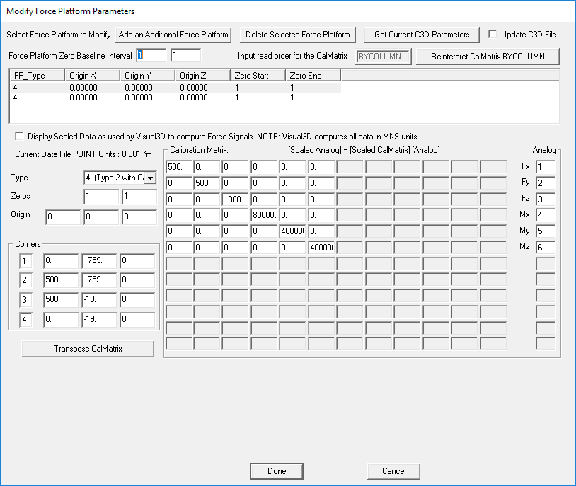
This dialogue box allows the user to alter the settings of the force plates.
Which force plate is being altered can be controlled using the buttons at the top of the dialogue box.
Add an Additional Force Platform - When this button is clicked another force platform is added to the table of force plates which is located directly below the Select Force Platform to Modify buttons.
Delete Selected Force Platform - When this button is clicked whichever force platform is selected in the table of force plates will be deleted.
Get Current C3D Parameters - When this button is clicked the force platform parameters are retrieved from the C3D file in order to populate the dialogue box.
Update C3D File - If this checkbox is selected then when changes are made and the Done button is clicked the changes in the dialogue box will be saved to the C3D file.
Table of Force Plates - The table of force plates lists all of the force plates that exist in the C3D files that have been loaded. The table includes the Force Plate Type, the Origin for the X, Y and Z axis, the Zero Start and the Zero End.
Display Scaled Data as used by Visual3D to compute Force Signals - If this check box is selected then the data that is displayed will be scaled as it is by Visual3D.
Force Plate General Settings - The settings on the left hand side of the dialogue box control the settings listed in the Table of Force Plates. This includes: the force plate type which can be set between types 1 and 9; the zero start and end points; and the origins for the X, Y and Z axis.
Corners - This section of the dialogue allows the user to enter the coordinates for the four force plate corners.
Calibration Matrix - This section allows the user to manually enter the force plate calibration matrix. This matrix is individual to force plate.
Analog - This section allows the user to specify where the Fx, Fy, Fz, Mx, My, and Mz signals are coming from.
Done - This button allows the user to save all the changes made to the dialogue box and close the dialogue box. If the Update C3D File is selected then the changes will also be applied to the C3D file.
Cancel - This button allows the user to close the dialogue box without saving any of the changes made.
