Coordinate System 2
| Language: | English • français • italiano • português • español |
|---|
Segment Definition
The strategy for defining the Segment Coordinate System (SCS) for a segment was derived from a strategy developed by Tom Kepple in the Physical Disabilities Branch at the National Institutes of Health and incorporated into the NIH MOVE3D software, which was the precursor to Visual3D.
|
Rules to define a SCS:
3) The SCS origin is located along the line connecting the segment ends (the SCS Z axis) at the segment's proximal joint. How the segment ends are defined is explained here. |
Introduction
Before building a model, it is important to understand how a Segment Coordinate System (SCS) is created in Visual3D.
To create a SCS:
1) The user must specify targets to identify the distal/proximal end of a segment, using the specified targets V3D will:
- A) Define the anatomical (or frontal) plane & identify the joint centers that lie on the anatomical plane
- B) Align the inferior/superior axis of the SCS between joint centers (the inferior/superior axis will lie along the anatomical plane)
2) Visual3D must create unit vectors to define the SCS
The targets chosen to define the distal/proximal ends of the segment will affect the location and orientation of the SCS.
This information can also be downloaded as a power point from here.
More information regarding segment coordinate systems can be found on the C-Motion YouTube channel.
Establishing the SCS X, Y and Z Axes
Step 1: The segment endpoints are calculated. These markers are used to determine the frontal plane of the segment coordinate system.
Step 2: The SCS Z axis is determined by the unit vector directed from the distal segment endpoint to the proximal segment endpoint.
Step 3: The SCS Y axis is determined by the unit vector that is perpendicular to both the frontal plane and the Z axis. This axis is directed posterior to anterior.
Step 4: The SCS X axis is determined by the application of the right hand rule. This axis is medial-lateral in orientation.
If a lab uses a different convention, the orientation of the SCS may be modified. An example of a modified coordinate system is if the SCS Z axis is directed from distal to proximal, the SCS X axis is directed from posterior to anterior, and the SCS Y axis is medial-lateral.
Establishing the SCS: Step 1
Visual3D first calculates the segment endpoints and defines the anatomical plane. As described here, there are many ways to calculate the segment endpoints. The relevance is that the targets used to define the segment end points, also determine the frontal plane of the SCS.
Segments can be defined using three or four border targets:
If three border targets are used to define a segment (proximal end: 1 joint center landmark; distal end: 1 lateral target; 1 lateral target to define orientation), Visual3D:
1) Defines a circle in the frontal plane (SCS XZ plane) at a distance of one radius from the border target
2) Establishes the segment end to be the point on the circle such that the vector from that end to the border target will be perpendicular to the vector connecting the two segment ends
NOTE: There are many different ways to define a segment using three border targets, this is just one example.
If four border targets are used to define a segment (proximal: 1 medial target, 1 lateral target; distal: 1 medial target, 1 lateral target), Visual3D:
1) Finds the midpoints between the medial and lateral targets
2) Uses a leastsquares method to define the frontal plane
Establishing the SCS: Step 2
The Z-axis (the inferior/superior axis) is defined by the vector from the distal segment endpoint to the proximal segment endpoint.

Establishing the SCS: Step 3
The Y-axis (the anterior/posterior axis) is projected forward in the anterior posterior direction.

Establishing the SCS: Step 4
The X-axis (the mediolateral axis) is perpendicular to the Y-Z plane.

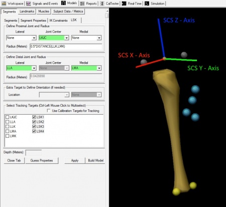
Establishing the SCS in V3D
|
This illustration shows what you might see when defining just one segment—the left shank. |
|
|
Segment Definition
The YouTube Tutorial on Segment Definition creates several coordinate systems for the shank segment using various targets to define the proximal and distal ends of the segment.


