Force Structures
| Language: | English • français • italiano • português • español |
|---|
Force Structures were conceived as a mechanism for combining force platform data (e.g. treating several contiguous platforms as a single platform), and for accommodating structures that are attached to the force platform as a super-structure such as the stairs manufactured by AMTI.
Our original implementation treated these "entities" as different FORCE_PLATFORM types, but this decision caused problems with other manufacturers that didn't recognize the new types. After consideration we determined that the introduction of a new C3D parameter group for FORCE_STRUCTURES was a more general solution because it didn't affect the force platform parameters.
Theory
External forces require the specification of 9 components
- Force= (Fx, Fy, Fz)
- Center of Pressure= (COPx, COPy, COPz)
- Free Moment= (Tx, Ty, Tz)
Only 6 pieces of information, however, are available from a force platform, so it is necessary to specify (or assume) 3 components.
For a typical platform:
- Tx and Ty are assumed to be zero. This means that we assume that the subject is not pulling up on the platform.
- COPz is assumed to be on the top surface of the platform.
For a surface (e.g. a step) placed on top of the force platform, the COP is translated along the Force Vector to the new surface. (e.g. the intersection of the force with the new surface).
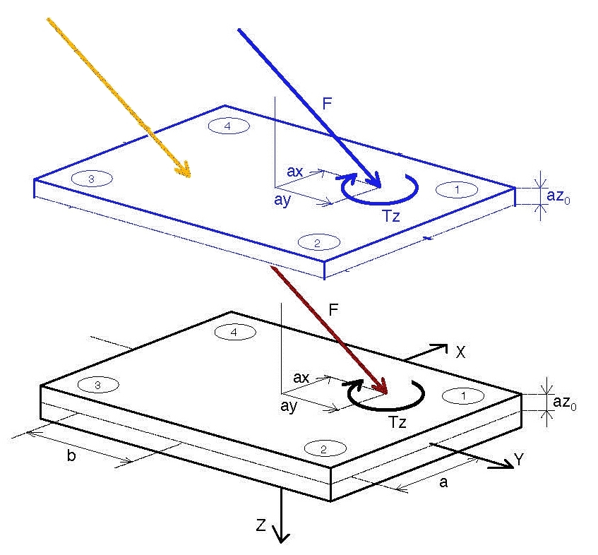
This figure shows a picture of an oblique force applied to a step. This figure shows one type of force platform, but the concept applies equally to all platforms.
The bottom platform represents the location of the force platform, with the recorded Ground Reaction Force (GRF) displayed as a red arrow.
The yellow vector represents the force structure force, which is colinear with the recorded GRF and intersects the force structure at the tip of the yellow arrow.
The raised platform (in blue) is displayed because this is the way that some labs have tried to implement the step. This figure represents the elevation of the original force platform corners to the step height. If the Force Platform ORIGIN vector is not modified (e.g. modify az0) so that it accurately represent the actual ORIGIN of the physical Force Platform, the blue vector on the raised surface is physically wrong by the displacement between the tip of the yellow vector and the tip of the blue vector.
If the ORIGIN vector is corrected appropriately, the yellow vector would be coincident and colinear with the blue vector.
Visual3D computes this intersection from the ORIGINAL FORCE and COP signals.
A consequence of this is that it is important to filter the ANALOG signals rather than filtering the FORCE, COP, and FREEMOMENT signals. Remember to select the Settings Option to use Processed Analog signals for computing the force vectors.
Pipeline Command
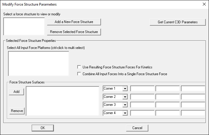
The edit dialog invoked either by selected Modify Force Structures under the Force Menu or by the Pipeline command Modify_Force_Structure_Parameters as follows.
Each structure is defined as a plane (or polygon) defined by four corners.
If the force structure is not a single plane, but multiple planes, each surface should be defined in the Force Structure Surfaces list box
Modify_Force_Structure_Parameters
- Modify_Force_Structure_Parameters
- /USED= Number of Force Structures Used
- ! /TYPE= Not currently used
- ! /NUM_FP_IN= Number of Force Platforms assigned to each force structure
- ! /FP_INDEX= Index number of each platform
- ! /NUM_SURFACES_OUT= Number of output surfaces for each force structure
- ! /SPEED_VALUES= the speed of the surface of each structure (e.g. an instrumented treadmill)
- ! /SPEED_CHANNELS= analog channel number for the speed of each structure
- ! /SPEED_SCALES= scale factor for the analog channel
- ! /CORNER1= corner locations for each output surface
- ! /CORNER2=
- ! /CORNER3=
- ! /CORNER4=
- /USE_FORCES_FOR_KINETICS= are forces kinematics only?
- /COMBINE_INPUT_FORCES= combine all forces for each structure into a single force
- ! /Update_C3D_File=FALSE
- ;
For example, the following force structure has one surface attached to two force platforms.
- Modify_Force_Structure_Parameters
- /USED=2
- /TYPE=0+0
- /NUM_FP_IN=2+1
- /FP_INDEX=2+3+4
- /NUM_SURFACES_OUT=2+2
- /SPEED_VALUES=0+0
- ! /SPEED_CHANNELS=
- ! /SPEED_SCALES=
- /CORNER1=1533.16+464.5+0+2038.16+464.5+355.6+1450+0.5+177.8+2017.84+0.5+533.4
- /CORNER2=1533.16+0.5+0+2038.16+0.5+355.6+1450+464.5+177.8+2017.84+464.5+533.4
- /CORNER3=1269+0.5+0+1774+0.5+355.6+1810+464.5+177.8+2282+464.5+533.4
- /CORNER4=1269+464.5+0+1774+464.5+355.6+1810+0.5+177.8+2282+0.5+533.4
- /USE_FORCES_FOR_KINETICS=TRUE+TRUE
- /COMBINE_INPUT_FORCES=TRUE+FALSE
- ! /UPDATE_C3D_FILE=FALSE
- ;
See also Modify_Force_Structure_Parameters
Structure consisting of 1 force platform and 2 surfaces
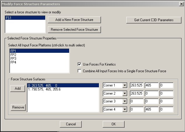
The following dialog creates a force structure that is comprised of 2 surfaces attached to the same platform.
Visual3D creates two surfaces, so it creates two force signals.
The signals appear in the data tree as:
- FS1_1 and FS1_2
which stands for Force Structure 1 Surface 1 and Force Structure 1 Surface 2.
Visual3D assigns the force computed from FP1 (in this case) to the surface that is intersected by the force.
The surface is defined by the four sided polygon defined by the corners.
The force assignments are included in the data tree.
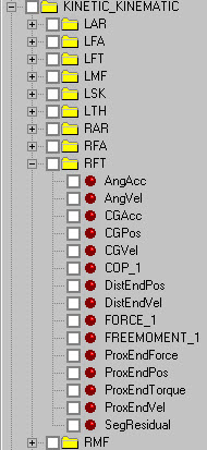
- COP_1, FORCE_1 and FREEMOMENT_1
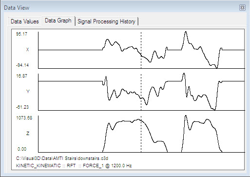
In the following figure the right foot makes contact with 2 steps
Structure consisting of 2 force platforms and 1 surface
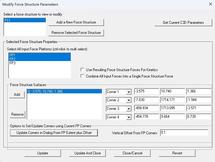
The following dialog creates a force structure that is comprised of 1 surface spanning 2 force platforms.
The user has the option to treat each force independently, which means that each force FP1 and FP2 could be assigned to the same segment.
The automatic gait events are search for segments that have been assigned a force, so if a foot steps on one platform at heel strike and a different platform at toe off, Visual3D will create 1 heel strike and 1 toe off event even though there are two different forces being used.
The inverse dynamics are computed correctly regardless of whether the two forces are combined into one force or left as two forces; Visual3D keeps track of the bookkeeping for the user.
The combined force is computed as follows:
- transform the force, Cop, and Free moment of each force platform into the output polygon (force structure surface) coordinate system
- solve the following 6 equations for the resultant force and moment
 solve for the 3 components of the force
 assume the resultant center of pressure lies on the output surface, and that the Free Moment is computed only about the normal to the surface
- solve for the x and y component of the COP on the surface
- solve for Tz of the Free Moment
- Transform these values back into the laboratory coordinate system
If there are two force platforms, the resulting signal will appear in the data tree as
- FS1_1 and FS1_2
This is interpreted as Force Structure 1 contribution from Force platform 1, and Force Structure 1contribution from force platform 2.
If, for example, instead of FP1 and FP2, there was FP1 and FP3, the signals would be
- FS1_1 and FS1_3
if the option to combine all input forces is selected, there will be one resulting signal
- FS1_1
Curved Surfaces
If the force structure is actually a continuous curved surface, it must be approximated by a series of contiguous surfaces.
