IK Kinematic Foot
| Language: | English • français • italiano • português • español |
|---|
Introduction
In this tutorial Virtual foot & Kinematic Only Foot are used interchangeably, but have the same meaning.
When using 6 DOF, user's commonly create a second kinematic only foot which represents neutral (0 degrees flexion/extension) when the foot is aligned with the floor. The reason for this is explained further here.
With an IK model, it is important that:
- The proximal end of the segment be defined as the point of rotation.
- This means that the kinematic only foot segments described in the Foot and Ankle Tutorial may not be appropriate.
- Only one version of each segment be included in the IK chain (otherwise, those tracking targets will be included in the POSE twice, giving them a higher weight than all other tracking targets).
- If this is done, it is important to change the weight of the segment in the IK POSE (this is done in Method 3).
Prior to the Tutorial
This tutorial assumes that you already have a model template, with an IK chain defined. The IK chain should include one kinetic foot segment.
A sample CMO file can be downloaded to use with this tutorial. To prepare this CMO file for the tutorial, the following steps were taken:
- Load the static trial, and apply the model template. Load the dynamic trial, and assign the model to the motion trial.
- The force assignments on FP4 and FP1 should be removed because the trial was cropped too short (the trial should not start/end with the subject's foot on the force platform).
- Created events in the dynamic trial:
- Start at frame 101
- End at frame 331
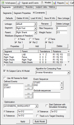
- In the Models tab, under the "IK constraints", click Defaults. Deselect "All Frames for Build" and select the sequence START+END. The IK will only run between these events in the dynamic trial.
- For this example, allow rotations about all three axes for the knee joint. Select the "Right Shank", and check Rot 2 and Rot 3. Select the "Left Shank", and check Rot 2 and Rot 3.
- Click "Build Model". The IK will run for all frames between START+END.
While modifying the model in this tutorial, it is recommended to set the POSE algorithm to 6 Degree of Freedom. By setting the POSE to 6 Degree of Freedom, the IK will not have to solve at each frame every time a change is made.
Creating Kinematic Only Foot
Method 1: Virtual Foot Tracked using 6 DOF
A completed example of this can be found here.
If you create a virtual foot, but do not include this foot in the IK chain, it will be tracked using 6 DOF. This means the kinetic foot in the IK chain and the virtual foot will be tracked differently since the POSE estimation is different.
If tracking the virtual foot using 6 DOF, any of the examples in the Foot and Ankle Tutorial may be used.
An example of this would be to create a foot which is parallel to the floor:
|
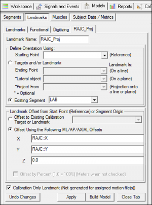
1. Create Right Ankle Joint Center Projected (RAJC_Proj):
|
|
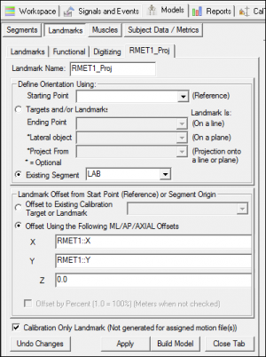
2. Create Right Metatarsus 1 Projected (RMET1_Proj):
|
|
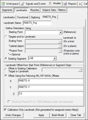
3. Create Right Right Metatarsus 5 Projected (RMET5_Proj):
|
|
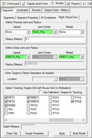
4. Create Right Virtual Foot Segment:
|
|
5. Rotate the Segment Coordinate system:
|
Method 2: Virtual Foot Tracked using IK Landmarks
A completed example of this can be found here.
This example creates landmarks which are tracked in the kinetic foot coordinate system. These landmarks are then used to track the virtual foot. This method assures there will not be any motion between the kinetic and virtual foot segments.
|
1-4. Create landmarks RAJC_Proj, RMET1_Proj, and RMET5_Proj
|
|
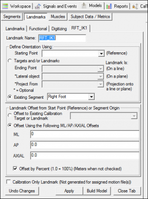
5. Create tracking target in the right kinetic foot coordinate system (RFT_IK1):
|
|
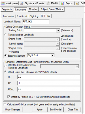
6. Create tracking target in the right kinetic foot coordinate system (RFT_IK2):
|
|
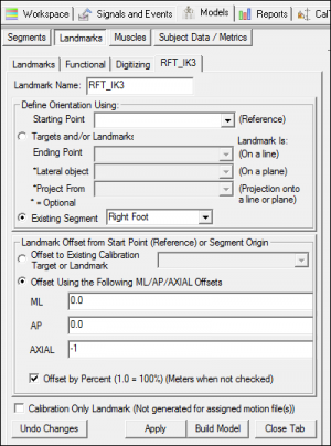
7. Create tracking target in the right kinetic foot coordinate system (RFT_IK3):
|
|
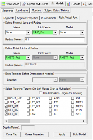
8. Create Right Virtual Foot Segment:
|
|
9. Rotate the Segment Coordinate system:
|
Method 3: Virtual Foot Tracked using Second IK Foot
A completed example of this can be found here.
If two right foot segments are added to the IK chain, this would mean the right foot targets are included in the POSE calculation twice. This would give the right foot targets a higher weight than all the other targets in the IK.
For this reason, when adding a second virtual foot to the IK, it is necessary to decrease the weight for the kinetic and virtual foot segments from 1 to 0.5 (half).
When defining a segment in the IK chain, it is important that the proximal end of the segment be the point of rotation. For this reason, the definition of the landmarks is slightly different than in Method 1 (where the foot was projected onto the ground).
|
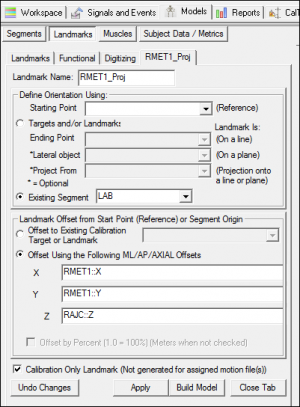
1. Create Right Metatarsus 1 Projected (RMET1_Proj):
|
|
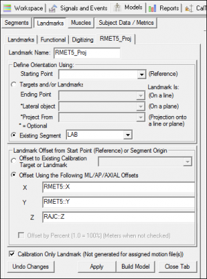
2. Create Right Metatarsus 5 Projected (RMET5_Proj):
|
|
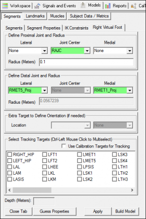
3. Create Right Virtual Foot Segment:
|
|
4. Rotate the Segment Coordinate system:
|
|
5. Set weighting for KINETIC foot to be 0.5:
|
|
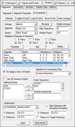
6. Add the VIRTUAL foot to the IK Chain:
|
NOTE: The Mobilizers (Degrees of Freedom), should match the degrees of freedom used for your kinetic foot segment.
So what's the difference
Each of the sample CMO files (all three can be downloaded) have two joint angles defined, ANGLE_BTWN_LFT and ANGLE_BTWN_RFT. These signals represent the joint angles between the virtual foot segment created using each method, and the kinetic foot segment.
For Method 1 and 3, you will notice that the angle between the virtual and kinetic foot segments does not change at the beginning/end of the trial. This is because the IK is only run between frames START+END, so at the beginning/end of the trial both foot segments are tracked using 6 degree of freedom, so they are the same.
|
For Method 1, the joint angle changes some between the virtual foot and kinetic foot segments since the kinetic foot is tracked using IK, while the virtual foot is tracked using 6 Degree of Freedom. |
|
For Method 2, the joint angle does not change between the virtual foot and kinetic foot segments. This is because the virtual foot is tracked using landmarks which are tracked by the kinetic foot segment. |
|
For Method 3, there is some motion in the joint angle between the foot and kinetic foot segments since both segments are included in the IK. |
