This tutorial describes the 2007 publication. For the updated 2014 IOR foot model see here.
Sample Data
Sample data can be downloaded here.
Once the zip file has been downloaded, you can find a static C3D and three dynamic trials in the SampleFiles folder. These files will be used to complete the tutorial.
The model, planar angles and joint angles for the right side were defined and plotted in the Leardini_2007_Angles.cmo. Once the left side angles have been defined, the report template will graph both the left and right angles.
Introduction
Visual3D is a general tool capable of implementing many different foot models.
This tutorial describes the IOR Foot analysis as it was published in the ORIGINAL paper (shown below):
- Leardini, A., M.G. Benedetti, L. Berti, D. Bettinelli, R. Nativo, and S. Giannini. "Rear-foot, Mid-foot and Fore-foot Motion during the Stance Phase of Gait." Gait & Posture 25 (2007): 453-55
Modifications were made to the original IOR Foot analysis (published in the paper below).
The modified tutorial can be found here.
- Portinaro, N., A. Leardini, A. Panou, V. Monzani, and P. Caravaggi. "Modifying the Rizzoli foot model to improve the diagnosis of pes-planus: application to kinematics of feet in teenagers." Journal of Foot and Ankle Research (2014)
Below is a tutorial demonstrating how to implement the ORIGINAL analysis in Visual3D. If you would rather see a fully completed model you can simply download the following file [blank] and open it in Visual3D.
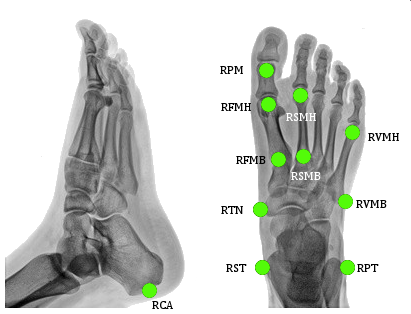
- CA[1](FCC) [2]:p. 160 = Posterior Surface of Calcaneus
- ST[1](FST)[2] = Sustentaculum Tali of Calcaneus
- PT[1](FPT)[2] = Lateral apex of the peroneal tubercle
- TN[1](FNT)[2] = Medial apex of the tuberosity navicular
- FMH[1](FM1)[2] = Head of 1st Metatarsus
- SMH[1](FM2)[2] = Head of 2nd Metatarsus
- VMH[1](FM5)[2] = Head of 5th Metatarsus
- VMB[1](FMT)[2] = Tuberosity of 5th Metatarsal
- PM[1](PM6)[2] = Proximal Medial Phalanx
- FMB[1] = Base of First Metatarsal
- SMB[1] = Base of Second Metatarsal
Metatarsus (Met)
Landmarks
|
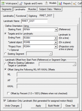
1. Create RMET_DIST:
- Click Landmarks button
- Click Add New Landmark button
- Create Landmark: RMET_DIST
|
Landmark Name: RMET_DIST
Define Orientation Using:
Starting Point: RFMH
Ending Point: RVMH
Lateral Object: RSMB
Project From: RSMH
|
|
- Do NOT Check: Offset by Percent (1.0 = 100%)
- Check: Calibration Only Landmark
|
|
Segment Definition
|
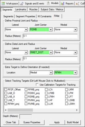
1. Create RMet Segment:
- In the Segments tab, select RMet in the Segment Name box.
- Select Kinematic Only
- Click on the Create Segment button.
- In the RMet tab, enter these values:
|
Define Proximal Joint and Radius
Lateral: None Joint: RSMB Medial: None
Radius: 0.1
Define Distal Joint and Radius
Lateral: None Joint: RMET_DIST Medial: None
Radius: 0.1
Extra Target to Define Orientation
Location: Medial RFMH
Select Tracking Targets:
RFMB, RFMH, RSMB, RSMH, RVMB, RVMH
|
|
- Click on Build Model.
- Click on Close Tab before proceeding.
|
|
The image to the right (and all other images in this tutorial) show a mediolateral view of the segment coordinate system after it has been modified.
Landmarks
|
1. Create RID Joint Center:
- Click Landmarks button
- Click Add New Landmark button
- Create Landmark: RID
|
Landmark Name: RID
Define Orientation Using:
Starting Point: RTN
Ending Point: RVMB
|
|
- Offset Using the Following AXIAL Offset: 0.5
- Check: Offset by Percent (1.0 = 100%)
- Check: Calibration Only Landmark
|

|
Segment Definition
|
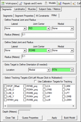
1. Create RMid Segment:
- In the Segments tab, select RMid in the Segment Name box.
- Select Kinematic Only.
- Click on the Create Segment button.
- In the RMid tab, enter these values:
|
Define Proximal Joint and Radius
Lateral: None Joint: RID Medial: None
Radius: 0.1
Define Distal Joint and Radius
Lateral: None Joint: RSMB Medial: None
Radius: 0.1
Extra Target to Define Orientation
Location: Medial RTN
Select Tracking Targets:
RSMB, RTN, RVMB
|
|
- Click on Build Model.
- Click on Close Tab before proceeding.
|
|
Calcaneus (Cal)
Landmarks
|
1. Create RIC Joint Center:
- Click Landmarks button
- Click Add New Landmark button
- Create Landmark: RIC
|
Landmark Name: RIC
Define Orientation Using:
Starting Point: RST
Ending Point: RPT
|
|
- Offset Using the Following AXIAL Offset: 0.5
- Check: Offset by Percent (1.0 = 100%)
- Check: Calibration Only Landmark
|

|
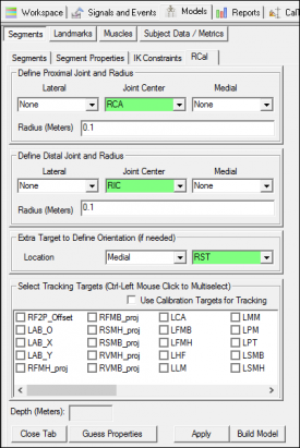
Segment Definition
|
1. Create RCal Segment:
- In the Segments tab, select RCal in the Segment Name box.
- Click on the Create Segment button.
- In the RCal tab, enter these values:
|
Define Proximal Joint and Radius
Lateral: None Joint: RCA Medial: None
Radius: 0.1
Define Distal Joint and Radius
Lateral: None Joint: RIC Medial: None
Radius: 0.1
Extra Target to Define Orientation
Location: Medial RST
Select Tracking Targets:
RCA, RPT, RST
|
|
- Click on Build Model.
- Click on Close Tab before proceeding.
|
|
Landmarks
|
1. Create RFT_DIST:
- Click Landmarks button
- Click Add New Landmark button
- Create Landmark: RFT_DIST
|
Landmark Name: RFT_DIST
Define Orientation Using:
Starting Point: RCA
Ending Point: RFMH
Lateral Object: RVMH
Project From: RSMH
|
|
- Do NOT Check: Offset by Percent (1.0 = 100%)
- Check: Calibration Only Landmark
|

|
Segment Definition
|
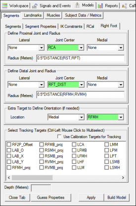
1. Create Right Foot Segment:
- In the Segments tab, select Right Foot in the Segment Name box.
- Click on the Create Segment button.
- In the Right Foot tab, enter these values:
|
Define Proximal Joint and Radius
Lateral: None Joint: RCA Medial: None
Radius: 0.5*DISTANCE(RST,RPT)
Define Distal Joint and Radius
Lateral: None Joint: RFT_DIST Medial: None
Radius: 0.5*DISTANCE(RFMH,RVMH)
Extra Target to Define Orientation
Location: Medial RFMH
Select Tracking Targets:
RCA, RFMH, RVMH
|
|
- Click on Build Model.
- Click on Close Tab before proceeding.
|
|
Shank (Sha)
Landmarks
|
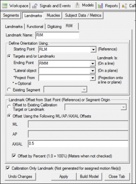
1. Create RIM:
- Click Landmarks button
- Click Add New Landmark button
- Create Landmark: RIM
|
Landmark Name: RIM
Define Orientation Using:
Starting Point: RLM
Ending Point: RMM
|
|
- Offset Using the Following AXIAL Offset: 0.5
- Check: Offset by Percent (1.0 = 100%)
- Check: Calibration Only Landmark
|
|
|
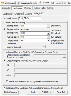
2. Create RSK_PROX:
- Click Landmarks button
- Click Add New Landmark button
- Create Landmark: RSK_PROX
|
Landmark Name: RSK_PROX
Define Orientation Using:
Starting Point: RIM
Ending Point: RLM
Lateral Object: RHF
Project From: RTT
|
|
- Do NOT Check: Offset by Percent (1.0 = 100%)
- Check: Calibration Only Landmark
|
|
Segment Definition
|
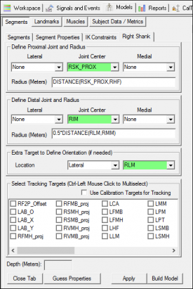
1. Create Right Shank Segment:
- In the Segments tab, select Right Shank in the Segment Name box.
- Click on the Create Segment button.
- In the Right Shank tab, enter these values:
|
Define Proximal Joint and Radius
Lateral: None Joint: RSK_PROX Medial: None
Radius: DISTANCE(RSK_PROX,RHF)
Define Distal Joint and Radius
Lateral: None Joint: RIM Medial: None
Radius: 0.5*DISTANCE(RLM,RMM)
Extra Target to Define Orientation
Location: Lateral RLM
Select Tracking Targets:
RHF, RLM, RMM, RTT
|
|
- Click on Build Model.
- Click on Close Tab before proceeding.
|
|
Angles
Landmarks
The F2Pt and F2Ps planar angles are calculated as the angle between the lines created by the targets FMB-FMH and FMH-PM. To calculate this angle using the Compute Planar Angle command, an offset along the line between FMB and FMH is created to define the 3 point angle.
|
1. Create RF2P_Offset:
- Click Landmarks button
- Click Add New Landmark button
- Create Landmark: RF2P_Offset
|
Landmark Name: RF2P_Offset
Define Orientation Using:
Starting Point: RFMB
Ending Point: RFMH
|
|
- Offset Using the Following AXIAL Offset: 1.5
- Check: Offset by Percent (1.0 = 100%)
- Do NOT Check: Calibration Only Landmark
|

|
|
2. Create LF2P_Offset:
- When defining the left signal, use same definitions as for the RF2P_Offset landmark
|
|
The F2G, S2G and V2G angles are calculated in the plane orthogonal to the ground. These landmarks will need to be projected onto the ground. To project landmarks onto the ground, the Lab_O, Lab_X and Lab_Y landmarks will need to be created to identify the plane of the ground.
|
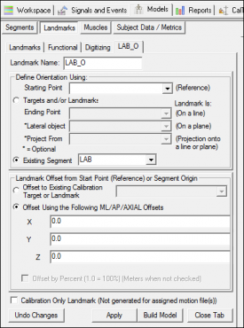
3. Create Lab_O:
- Click Landmarks button
- Click Add New Landmark button
- Create Landmark: Lab_O
- Offset Using the Following ML/AP/AXIAL Offsets:
X: 0.0
Y: 0.0
Z: 0.0
- Do NOT Check: Offset by Percent (1.0 = 100%) (Meters when not checked)
- Do NOT Check: Calibration Only Landmark (Not generated for assigned motion file(s))
|
|
|
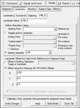
4. Create Lab_X:
- Click Landmarks button
- Click Add New Landmark button
- Create Landmark: Lab_X
- Offset Using the Following ML/AP/AXIAL Offsets:
X: 0.05
Y: 0.0
Z: 0.0
- Do NOT Check: Offset by Percent (1.0 = 100%) (Meters when not checked)
- Do NOT Check: Calibration Only Landmark (Not generated for assigned motion file(s))
|
|
|
5. Create Lab_Y:
- Click Landmarks button
- Click Add New Landmark button
- Create Landmark: Lab_Y
- Offset Using the Following ML/AP/AXIAL Offsets:
X: 0.0
Y: 0.05
Z: 0.0
- Do NOT Check: Offset by Percent (1.0 = 100%) (Meters when not checked)
- Do NOT Check: Calibration Only Landmark (Not generated for assigned motion file(s))
|

|
|
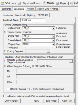
6. Create RFMH_proj:
- Click Landmarks button
- Click Add New Landmark button
- Create Landmark: RFMH_proj
|
Landmark Name: RFMH_proj
Define Orientation Using:
Starting Point: LAB_O
Ending Point: LAB_X
Lateral Object: LAB_Y
Project From: RFMH
|
|
- Do NOT Check: Offset by Percent (1.0 = 100%)
- Do NOT Check: Calibration Only Landmark
|
|
Create landmarks 7-17 by following the same format as the RFMH_proj landmark for:
|
7. RFMB
8. RSMH
9. RSMB
10. RVMH
11. RVMB
|
12. LFMH
13. LFMB
14. LSMH
15. LSMB
16. LVMH
17. LVMB
|
Planar Angles
F2Pt
F2Pt - the angle between the lines FMH-PM and FMB-FMH
projected onto the transverse plane of the metatarsus
Represents - valgus of the first metatarsophalangeal joint
|
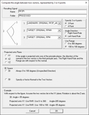
1. Create RF2Pt planar angle:
- Define Resulting Signal Name: RF2Pt
- Calculate a 3 point angle between the following targets:
|
1 - LANDMARK::ORIGINAL::RF2P_offset
2 - TARGET::ORIGINAL::RFMH
3 - TARGET::ORIGINAL::RPM
Angle Direction: Left Hand Rule
Use Range: -180 to 180 degrees
Projected onto Plane: XZ
Note: The reference segment will need to be changed to RMet within the text option.
|
|
|
|
|
2. Create LF2Pt planar angle:
- When defining the left signal, use same definitions except set:
|
Angle Direction: Right Hand Rule
Note: The reference segment will need to be changed to LMet within the text option.
|
|
S2F
S2F - the angle between the lines FMB-FMH and SMB-SMH
projected onto the transverse plane of the metatarsus
|
1. Create RS2F planar angle:
- Define Resulting Signal Name: RS2F
- Calculate a 4 point angle between the following targets:
|
1 - TARGET::ORIGINAL::RSMH
2 - TARGET::ORIGINAL::RSMB
3 - TARGET::ORIGINAL::RFMB
4 - TARGET::ORIGINAL::RFMH
Angle Direction: Right Hand Rule
Use Range: -180 to 180 degrees
Projected onto Plane: XZ
Note: The reference segment will need to be changed to RMet within the text option.
|
|
|

|
|
2. Create LS2F planar angle:
- When defining the left signal, use same definitions except set:
|
Angle Direction: Left Hand Rule
Note: The reference segment will need to be changed to LMet within the text option.
|
|
S2V
S2V - the angle between the lines VMB-VMH and SMB-SMH
projected onto the transverse plane of the metatarsus
|
1. Create RS2V planar angle:
- Define Resulting Signal Name: RS2V
- Calculate a 4 point angle between the following targets:
|
1 - TARGET::ORIGINAL::RSMH
2 - TARGET::ORIGINAL::RSMB
3 - TARGET::ORIGINAL::RVMB
4 - TARGET::ORIGINAL::RVMH
Angle Direction: Right Hand Rule
Use Range: -180 to 180 degrees
Projected onto Plane: XZ
Note: The reference segment will need to be changed to RMet within the text option.
|
|
|

|
|
2. Create LS2V planar angle:
- When defining the left signal, use same definitions except set:
|
Angle Direction: Left Hand Rule
Note: The reference segment will need to be changed to LMet within the text option.
|
|
F2G
F2G - the angle between the lines FMB-FMH and the ground,
plane orthogonal to the ground (3D angle relative to the ground)
The FMH_proj and FMB_proj landmarks will be used to calculate the F2G planar angle which are described in the landmarks section.
|
1. Create RF2G planar angle:
- Define Resulting Signal Name: RF2G
- Calculate a 4 point angle between the following targets:
|
1 - TARGET::ORIGINAL::RFMB
2 - TARGET::ORIGINAL::RFMH
3 - TARGET::ORIGINAL::RFMH_proj
4 - TARGET::ORIGINAL::RFMB_proj
Angle Direction: Right Hand Rule
3D Space: Always 0 to 180 degrees
|
|
|

|
|
2. Create LF2G planar angle:
- When defining the left signal, use same definitions as for the right angle
|
S2G
S2G - the angle between the lines SMB-SMH and the ground,
plane orthogonal to the ground (3D angle relative to the ground)
The SMH_proj and SMB_proj landmarks will be used to calculate the S2G planar angle which are described in the landmarks section.
|
1. Create RS2G planar angle:
- Define Resulting Signal Name: RS2G
- Calculate a 4 point angle between the following targets:
|
1 - TARGET::ORIGINAL::RSMB
2 - TARGET::ORIGINAL::RSMH
3 - TARGET::ORIGINAL::RSMH_proj
4 - TARGET::ORIGINAL::RSMB_proj
Angle Direction: Right Hand Rule
3D Space: Always 0 to 180 degrees
|
|
|

|
|
2. Create LS2G planar angle:
- When defining the left signal, use same definitions as for the right angle
|
V2G
V2G - the angle between the lines VMB-VMH and the ground,
plane orthogonal to the ground (3D angle relative to the ground)
The VMH_proj and VMB_proj landmarks will be used to calculate the V2G planar angle which are described in the landmarks section.
|
1. Create RV2G planar angle:
- Define Resulting Signal Name: RV2G
- Calculate a 4 point angle between the following targets:
|
1 - TARGET::ORIGINAL::RVMB
2 - TARGET::ORIGINAL::RVMH
3 - TARGET::ORIGINAL::RVMH_proj
4 - TARGET::ORIGINAL::RVMB_proj
Angle Direction: Right Hand Rule
3D Space: Always 0 to 180 degrees
|
|
|

|
|
2. Create LV2G planar angle:
- When defining the left signal, use same definitions as for the right angle
|
F2Ps
F2Ps - the angle between the lines FMH-PM and FMB-FMH
projected onto the sagittal plane of the metatarsus
Represents - dorsiflexion of the first metatarso-phalangeal joint
|
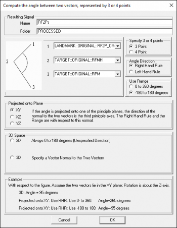
1. Create RF2Ps planar angle:
- Define Resulting Signal Name: RF2Ps
- Calculate a 3 point angle between the following targets:
|
1 - LANDMARK::ORIGINAL::RF2P_offset
2 - TARGET::ORIGINAL::RFMH
3 - TARGET::ORIGINAL::RPM
Angle Direction: Right Hand Rule
Use Range: -180 to 180 degrees
Projected onto Plane: XY
Note: The reference segment will need to be changed to RMet within the text option.
|
|
|
|
|
2. Create LF2Ps planar angle:
- When defining the left signal, use same definitions as for the right angle
|
Note: The reference segment will need to be changed to LMet within the text option.
|
|
MLA
MLA - the angle between the lines CA-ST and ST-FMH
projected onto the sagittal plane of the foot
Represents - navicular drop
|
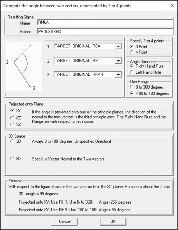
1. Create RMLA planar angle:
- Define Resulting Signal Name: RMLA
- Calculate a 3 point angle between the following targets:
|
1 - TARGET::ORIGINAL::RCA
2 - TARGET::ORIGINAL::RST
3 - TARGET::ORIGINAL::RFMH
Angle Direction: Right Hand Rule
Use Range: -180 to 180 degrees
Projected onto Plane: XY
Note: The reference segment will need to be changed to RMet within the text option.
|
|
|
|
|
2. Create LMLA planar angle:
- When defining the left signal, use same definitions as for the right angle
|
Note: The reference segment will need to be changed to LMet within the text option.
|
|
Joint Angles
Sha_Foo_Angle
|
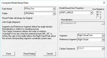
1. Define the RSha_Foo_Angle:
- Open the Compute Model Based dialog
- Select JOINT_ANGLE from drop down list
|
Data Name: RSha_Foo_Angle
Segment: Right Foot
Reference Segment: Right Shank
Cardan Sequence: Z-X-Y
|
|
- Use Negative:
X: TRUE
Y: TRUE
Z: FALSE
|
|
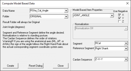
Sha_Cal_Angle
|
1. Define the RSha_Cal_Angle:
- Open the Compute Model Based dialog
- Select JOINT_ANGLE from drop down list
|
Data Name: RSha_Cal_Angle
Segment: RCal
Reference Segment: Right Shank
Cardan Sequence: Z-X-Y
|
|
- Use Negative:
X: TRUE
Y: TRUE
Z: FALSE
|
|
Cal_Mid_Angle
|
1. Define the RCal_Mid_Angle:
- Open the Compute Model Based dialog
- Select JOINT_ANGLE from drop down list
|
Data Name: RCal_Mid_Angle
Segment: RMid
Reference Segment: RCal
Cardan Sequence: Z-X-Y
|
|
- Use Negative:
X: TRUE
Y: TRUE
Z: FALSE
|

|
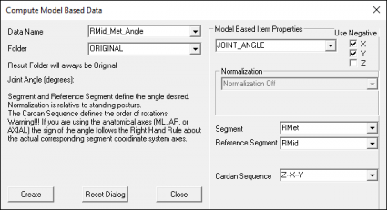
Mid_Met_Angle
|
1. Define the RMid_Met_Angle:
- Open the Compute Model Based dialog
- Select JOINT_ANGLE from drop down list
|
Data Name: RMid_Met_Angle
Segment: RMet
Reference Segment: RMid
Cardan Sequence: Z-X-Y
|
|
- Use Negative:
X: TRUE
Y: TRUE
Z: FALSE
|
|
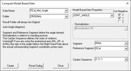
Cal_Met_Angle
|
1. Define the RCal_Met_Angle:
- Open the Compute Model Based dialog
- Select JOINT_ANGLE from drop down list
|
Data Name: RCal_Met_Angle
Segment: RMet
Reference Segment: RCal
Cardan Sequence: Z-X-Y
|
|
- Use Negative:
X: TRUE
Y: TRUE
Z: FALSE
|
|
References
- ↑ 1.00 1.01 1.02 1.03 1.04 1.05 1.06 1.07 1.08 1.09 1.10 Leardini, A., M.G. Benedetti, L. Berti, D. Bettinelli, R. Nativo, and S. Giannini. "Rear-foot, Mid-foot and Fore-foot Motion during the Stance Phase of Gait." Gait & Posture 25 (2007): 453-55
- ↑ 2.0 2.1 2.2 2.3 2.4 2.5 2.6 2.7 2.8 Serge van Sint Jan "Color Atlas of Skeletal Landmark Definitions: Guidelines for Reproducible Manual and Virtual Palpations" 2007 - Churchill Livingstone


