IORFoot Tutorial Original
| Language: | English • français • italiano • português • español |
|---|
This tutorial has been updated to match the naming convention used in the 2007 IOR foot paper. The MODIFIED tutorial can be found here.
In 2014, updates to the IOR foot model were published. The 2014 tutorial can be found here.
Visual3D is a general tool capable of implementing many different foot models.
This tutorial focuses on the multi-segment foot model as described in the following article:

Below is a tutorial demonstrating how this is done in Visual3D. If you would rather see a fully completed model you can simply download the following file [blank] and open it in Visual3D.
Multi-Segment Foot Marker Set

- CA[1](FCC) [2]:p. 160 = Posterior Surface of Calcaneus
- ST[1](FST)[2] = Sustentaculum Tali of Calcaneus
- PT[1](FPT)[2] = Lateral apex of the peroneal tubercle
- TN[1] (FNT) [2] = Medial apex of the tuberosity navicular.
- FMH[1](FM1)[2] = Head of 1st Metatarsus
- SMH[1](FM2)[2] = Head of 2nd Metatarsus
- VMH[1](FM5)[2] = Head of 5th Metatarsus
- VMB[1](FMT)[2] = Tuberosity of 5th Metatarsal
- PM[1](PM6)[2] = Proximal Medial Phalanx
- FMB[1] = Base of First Metatarsal
- SMB[1] = Base of Second Metatarsal
Download and open the c3d files in Visual3D
Download the zip file IORfoot_Tutorial.zip containing the .c3d files.
Unzip this file in a location of your choice.
From the File menu select Open.
From the "Open the movement trial" dialog navigate to the files you downloaded and select the file labeled IORfoot_Walk1.c3d, IORfoot_Walk2.c3d and IORfoot_Walk3.c3d. Click Open.
Note: If you would like to perform your own motion capture for this model, here is a list of the marker names in this file: LFM_MARKERS.txt
Create a hybrid model - From the Model menu open Create (Add Static Calibration File) and select Visual3D Hybrid Model.
Load the standing trial - From the "Select the calibration file for the new model" dialog box select the file labeled IORfoot_Static1.c3d and click Open.
Assign the model to the movement trial - When the "Assign Models to Motion Data" window opens select the movement files IORfoot_Walk1.c3d, IORfoot_Walk2.c3d and IORfoot_Walk3.c3d and click OK.
Visual3D will automatically open the Model Builder mode and your screen should look like the image below.
Creating the landmarks
The Leardini Foot Model is built using landmarks and motion capture markers. Landmarks are defined relative to motion capture markers, other landmarks, or to existing segment coordinate systems.
Note: As you go through this exercise, you will notice that the marker names in our example are slightly different than those shown above.
Project TARGET onto the Laboratory Floor
In order to calculate the sagittal planar angles, certain markers/targets must be projected onto the floor.
- Open the Landmarks Tab
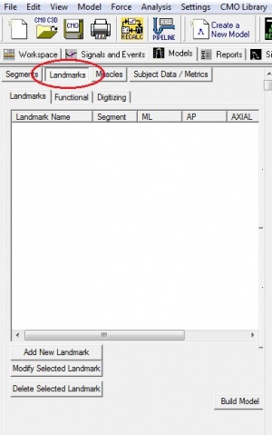
- Click Add a New Landmark
- In the box labeled Landmark Name, enter LFM_FLOOR
- Leave all boxes empty, except for the box labeled Existing Segment select Lab (it should already be selected)
- Click the radio button labeled Offset Using the Following ML/AP/AXIAL offsets
- Enter LFM::X, LFM::Y and 0 for the X, Y and Z offsets respectively.
- Click Apply. when all the information (listed below) has been entered
- Click Close Tab.
- Click Add a New Landmark
- In the field. labeled Landmark Name enter the name of the marker/target LIC (RIC).
- From the list box labeled Starting Point select LST (RST).
- Click the radio button labeled Targets and/or Landmarks.
- From the list box labeled Ending Point select LPT (RPT).
- Click the radio button labeled Offset Using the Following AP/ML/AXIAL Offsets
- In the field labeled AXIAL enter 0.5.
- Check the checkbox labeled Offset by Percent (1.0 = 100%) (Meters when not checked).
- Click Apply.
- Click Close Tab.
- Click Add a New Landmark
- In the field. labeled Landmark Name enter the name of the marker/target LID (RID).
- From the list box labeled Starting Point select LTN (RTN).
- Click the radio button labeled Targets and/or Landmarks.
- From the list box labeled Ending Point select LVMB (RVMB).
- Click the radio button labeled Offset Using the Following AP/ML/AXIAL Offsets
- In the field labeled AXIAL enter 0.5.
- Check the checkbox labeled Offset by Percent (1.0 = 100%) (Meters when not checked).
- Click Apply.
- Click Close Tab.
- Click Add a New Landmark
- In the field. labeled Landmark Name enter the name of the marker/target LIM (RIM).
- From the list box labeled Starting Point select LLM (RLM).
- Click the radio button labeled Targets and/or Landmarks.
- From the list box labeled Ending Point select LMM (RMM).
- Click the radio button labeled Offset Using the Following AP/ML/AXIAL Offsets
- In the field labeled AXIAL enter 0.5.
- Check the checkbox labeled Offset by Percent (1.0 = 100%) (Meters when not checked).
- Click Apply.
- Click Close Tab.
- Click Add a New Landmark
- In the field. labeled Landmark Name enter the name of the marker/target LSM_MET (RSM_MET).
- From the list box labeled Starting Point select LSMB (RSMB).
- Click the radio button labeled Targets and/or Landmarks.
- From the list box labeled Ending Point select LFM (RFM).
- From the list box labeled *Lateral object select LVM (RVM).
- From the list box labeled *Projected From select LSM (RSM).
- Click Apply.
- Click Close Tab.
- Click Add a New Landmark
- In the field. labeled Landmark Name enter the name of the marker/target LSM_FT (RSM_FT).
- From the list box labeled Starting Point select LCA (RCA).
- Click the radio button labeled Targets and/or Landmarks.
- From the list box labeled Ending Point select LFM (RFM).
- From the list box labeled *Lateral object select LVM (RVM).
- From the list box labeled *Projected From select LSM (RSM).
- Click Apply.
- Click Close Tab.
- Click Add a New Landmark
- In the field. labeled Landmark Name enter the name of the marker/target LF2P (RF2P).
- From the list box labeled Starting Point select LFMB (RFMB).
- Click the radio button labeled Targets and/or Landmarks.
- From the list box labeled Ending Point select LFM (RFM).
- Click the radio button labeled Offset Using the Following AP/ML/AXIAL Offsets
- In the field labeled AXIAL enter 1.5.
- Check the checkbox labeled Offset by Percent (1.0 = 100%) (Meters when not checked).
- Click Apply.
- Click Close Tab.
- Click Add a New Landmark
- In the field. labeled Landmark Name enter the name of the marker/target LSHANK_ORIGIN (RSHANK_ORIGIN).
- In the list box labeled Starting Point, enter LHF (RHF).
- In the list box labeled Ending Point, enter LLM(RLM).
- In the list box labeled Lateral Object, enter LMM (RMM).
- In the list box labeled Projected From, enter LTT (RTT).
- Click Apply.
- Click Close Tab.
- Click Add a New Landmark
- In the field. labeled Landmark Name enter the name of the marker/target LCAB_MLA (RCAB_MLA).
- From the list box labeled Starting Point select LCAB (RCAB).
- Click the radio button labeled Existing Segment.
- From the list box, select LT_CALC (RT_CALC).
- Click Apply.
- Click Close Tab.
- Follow the sub-steps below to create the shank segments using the following properties. The Shank segments are created by defining the KNEE (LT_KNEE/RT_KNEE) landmark as the proximal segment endpoint and the ANKLE joint centre (LIM/RIM) as the distal segment endpoint. The frontal plane is defined using the segment endpoints and the lateral malleolus (LLM/RLM) targets. The segment is tracked using the four shank markers.
- Click the Segments button to open the Segments tab.
- From the Segment Name list box select Left Shank (Right Shank).
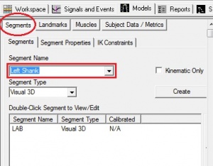
- Click Create. The segment will be created and the Left Shank tab will open.
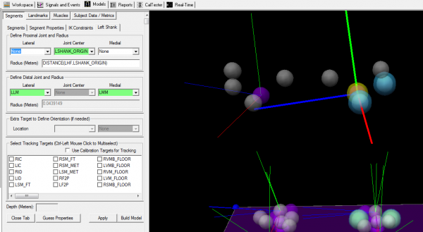
- In the section labeled Define Proximal Joint and Radius, select LSHANK_ORIGIN (RSHANK_ORIGIN) from the list box labeled Joint Center and enter DISTANCE(LHF,LSHANK_ORIGIN) (DISTANCE(RHF,RSHANK_ORIGIN)) in the Radius (Meters) field.
- In the section labeled Define Distal Joint and Radius, select LLM (RLM) from the list box labeled Lateral and LMM (RMM) in the list box labeled Medial.
- In the section labeled Select Tracking Targets, select the following targets: LHF (RHF), LLM (RLM), LMM (RMM) and LTT (RTT).
Note: Use the ctrl key on your keyboard while you click to select multiple targets. - Click Build Model.
- Click Close Tab.
- Click the Segment Properties button.
- From the Segment Name list box select Left Shank.
- Click the Modify Segment Coordinate System button.
- For the A/P Axis, select +X, and for the Distal to Proximal, select +Y.
- Then click OK.
- Then click Apply.
- Click the Segments button to open the Segments tab.
- From the Segment Name list box select Left Foot (Right Foot).
- Click Create. The segment will be created and the Left Foot tab will open.
- In the section labeled Define Proximal Joint and Radius, select LCA (RCA) from the list box labeled Joint and enter 0.5*DISTANCE(LPT,LST) (0.5*DISTANCE(RPT,RST) in the Radius (Meters) field.
- In the section labeled Define Distal Joint and Radius, select LSM_FT (RSM_FT) from the list box labeled Joint and enter 0.5*DISTANCE(LST,LPT) (0.5*DISTANCE(RPT,RST)) in the Radius (Meters) field.
- In the section labeled Extra Target to Define Orientation (if needed) , select Lateral and LVM (RVM) from the list boxes labeled Location.
- In the section labeled Select Tracking Targets, select the following targets: LSM_FT (RSM_FT), LCA (RCA) and LFM (RFM).
Note: Use the ctrl key on your keyboard while you click to select multiple targets. - Click Build Model.
- Click Close Tab.
- Click the Segment Properties button.
- Click the Modify Segment Coordinate System button.
- For the A/P Axis, select +Y, and for the Distal to Proximal, select -X.
- Then click OK.
- Then click Apply.
- The Foot Segment Coordinate system should now be similar to the Shank one.
- Click the Segments button to open the Segments tab.
- In the Segment Name box write LT_CALC (RT_CALC), and check the "Kinematic Only" box.
- Click Create. The segment will be created and the LT_CALC (RT_CALC) tab will open.
- In the section labeled Define Proximal Joint and Radius, select LCA (RCA) from the list box labeled Joint and enter 0.1 in the Radius (Meters) field..
- In the section labeled Define Distal Joint and Radius, select LIC (RIC) from the list box labeled Joint and enter 0.1 in the Radius (Meters) field.
- In the section labeled Extra Target to Define Orientation, select Medial from the list box labeled Location and LST (RST) from the second list box.
- In the section labeled Select Tracking Targets, select the following targets: LCA (RCA), LPT (RPT) and LST (RST).
Note: Use the ctrl key on your keyboard while you click to select multiple targets. - Click the Segment Properties button.
- Click the Modify Segment Coordinate System button.
- For the A/P Axis, select +Y, and for the Distal to Proximal, select -X.
- Then click OK.
- Then click Apply.
- Then click on the LT_CALC (RT_CALC) tab.
- Click Build Model.
- Click Close Tab.
- Click the Segments button to open the Segments tab.
- In the Segment Name box write LT_MID (RT_MID), and check the "Kinematic Only" box.
- Click Create. The segment will be created and the LT_MID (RT_MID) tab will open.
- In the section labeled Define Proximal Joint and Radius, select LID (RID) from the list box labeled Joint and enter 0.1 in the Radius (Meters) field.
- In the section labeled Define Distal Joint and Radius, select LSMB (RSMB) from the list box labeled Joint and enter 0.1 in the Radius (Meters) field.
- In the section Extra Target to Define Orientation (if needed), select Medial for the Location and LTN (RTN) as the target from the list box.
- In the section labeled Select Tracking Targets, select the following targets: LSMB (RSMB), LTN (RTN) and LVMB (RVMB).
Note: Use the ctrl key on your keyboard while you click to select multiple targets. - Click the Segment Properties button.
- Click the Modify Segment Coordinate System button.
- For the A/P Axis, select +Y, and for the Distal to Proximal, select -X.
- Then click OK.
- Then click Apply.
- Then click on the LT_MID (RT_MID) tab.
- Click Build Model.
- Click Close Tab.
- Click the Segments button to open the Segments tab.
- In the Segment Name box write LT_MET (RT_MET), and check the "Kinematic Only" box.
- Click Create. The segment will be created and the LT_MET (RT_MET) tab will open.
- In the section labeled Define Proximal Joint and Radius, select LSMB (RSMB) from the list box labeled Joint and enter 0.1 in the Radius (Meters) field.
- In the section labeled Define Distal Joint and Radius, select LSM_MET (RSM_MET) from the list box labeled Joint and select LVM (RVM) as the Lateral distal endpoint. The Radius will be automatically calculated based on those targets.
- In the section labeled Select Tracking Targets, select the following targets: LFM (RFM), LSMB (RSMB), LSM (RSM) and LVM (RVM).
Note: Use the ctrl key on your keyboard while you click to select multiple targets. - Click Build Model.
- Click Close Tab.
- Click the Segment Properties button.
- Click the Modify Segment Coordinate System button.
- For the A/P Axis, select +Y, and for the Distal to Proximal, select -X.
- Then click OK.
- Then click Apply.
- Then click on the LT_MET (RT_MET) tab.
- Click Build Model.
- Click Close Tab.
- F2Pt = angle between the projections of the line segments FMH-PM and FMB-FMH into the transverse plane of the metatarsus, positive angle with the former rotating laterally with respect to the latter, i.e. motion in valgus of the first metatarsophalangeal joint.
- S2F = angle between the projections of the line segments FMB-FMH and SMB-SMH into the transverse plane of the metatarsus, positive angle with the former rotating medially with respect to the latter.
- S2V = angle between the projections of the line segments VMB-VMH and SMB-SMH into the transverse plane of the metatarsus, positive angle with the former rotating laterally with respect to the latter.
- F2G = angle between the line segment FMB-FMH and the ground, i.e. in the plane orthogonal to the ground and containing FMB-FMH, positive angle with the downward rotation of the head.
- S2G = angle between the line segment SMB-SMH and the ground, positive angle with the downward rotation of the head.
- V2G = angle between the line segments VMB-VMH and the ground, positive angle with the downward rotation of the head.
- F2Ps = angle between the projections of the line segments FMH-PM and FMB-FMH into the sagittal plane of the metatarsus, positive angle with the former rotating upward, i.e. dorsiflexion of the first metatarso-phalangeal joint.
- MLA = angle between the projections of the line segments CA-ST and ST-FMH into the sagittal plane of the foot, positive angle with clockwise rotation of the former toward the latter, i.e. navicular drop being positive. This would replicate somehow what is known in radiography as the Moreau and Costa Bertani angle. To make sure all three markers (CA, ST and FMH)are not colinear, it is recommended to use the CAB marker instead of the CA since the CAB is lower than the CA marker, ensuring the angle is more acute.
- ↑ 1.00 1.01 1.02 1.03 1.04 1.05 1.06 1.07 1.08 1.09 1.10 1.11 Leardini, A., M.G. Benedetti, L. Berti, D. Bettinelli, R. Nativo, and S. Giannini. "Rear-foot, Mid-foot and Fore-foot Motion during the Stance Phase of Gait." Gait & Posture 25 (2007): 453-55
- ↑ 2.0 2.1 2.2 2.3 2.4 2.5 2.6 2.7 2.8 Serge van Sint Jan "Color Atlas of Skeletal Landmark Definitions: Guidelines for Reproducible Manual and Virtual Palpations" 2007 - Churchill Livingstone


The same steps should be repeated to create all subsequent landmarks representing floor projection of the following markers/targets, only replacing the name of the landmark's name ***_FLOOR and the X and Y offsets to the corresponding target:
LFM, LFMB, LSM, LSMB, LVM, LVMB, RFM, RFMB, RSM, RSMB, RVM, RVMB.
Creating other LANDMARKS
Other landmarks are also required to create certain segments.
![]()
The following landmarks need to be created:
LIC, RIC, LID, RID, LIM, RIM, LF2P, RF2P, LSM_FT, RSM_FT, LST_MET, RSM_MET, LCAB_MLA, RCAB_MLA, LIC_VIRTUAL, RIC_VIRTUAL, LST_VIRTUAL, RST_VIRTUAL, LSHANK_ORIGIN, RSHANK_ORIGIN.
Note: The contralateral landmarks have been paired together so that the parameters for the right landmarks included within parentheses next to the corresponding left parameter.
LIC (RIC):
Note: The LIC (RIC) landmarks defines the midpoint between the LST (RST) and the LPT (RPT) targets.
LID (RID):
Note: The LID (RID) landmark defines the midpoint between the LTN (RTN) and the LVMB (RVMB) targets.
LIM (RIM):
Note: The LIM (RIM) landmark defines the ankle joint centre based on the midpoint between the LLM (RLM) and the LMM (RMM) targets.
LSM_MET (RSM_MET):
Note: The LSM_MET (RSM_MET) landmark is the projection of the LSM (RSM) target onto the plane defined by the LSMB (RSMB), LFM (RFM) and the LVM (RVM) targets.
LSM_FT (RSM_FT):
Note: The LSM_FT (RSM_FT) landmark is the projection of the LSM (RSM) target onto the plane defined by the LCA(RCA), LFM (RFM) and the LVM (RVM) targets.
LF2P (RF2P):
Note: The LF2P (RF2P) is a landmark onto the line define by the LFMB (RFMB) and the LFM (RFM) targets.
LSHANK_ORIGIN (RSHANK_ORIGIN):
LCAB_MLA (RCAB_MLA):
Note: This landmark can only be created once the LT_CALC (RT_CALC) segment has been created.
Note: The LCAB_MLA (RCAB_MLA) landmark recreates the LCAB marker which is normally removed after the standing trial.
Defining the segments
Defining the Shank


Defining the Foot (single segment)
Follow the sub-steps below to create the foot segments (rigid segment) using the following properties. The Foot segments are created by defining the Calcaneus (LCA/RCA) targets as the proximal segment endpoint and the second metatarsal distal head (LSM/RSM) as the distal segment endpoint. The transverse plane is defined using the segment endpoints and the fifth metatarsal head (LVM/RVM) targets. The segment is tracked using three markers.


Defining the Foot Segments
The definition of the foot segments are as followed:

Defining the Calcaneus
Follow the sub-steps below to create the Calcaneus segments using the following properties.

Defining the Mid-foot
Follow the sub-steps below to create the Mid-Foot segments using the following properties. The Mid-Foot segments are created by defining the LID (RID) landmark as the proximal segment endpoint and the LSMB (RSMB) as the distal segment endpoint. The transverse plane is defined using the segment endpoints and the LTN/RTN targets. The segment is tracked using three markers.
Defining the Metatarsus
Follow the sub-steps below to create the Metatarsus segments using the following properties. The Metatarsus segments are created by defining the LSMB (RSMB) landmark as the proximal segment endpoint, the LSM_MET (RSM_MET) as the distal segment joint and the LVM/RVM as the lateral distal endpoint. The segment is tracked using four markers.
Computing Planar Angles
The IOR multi-segment foot model also offers a method to measure foot planar/anatomical angles, often measured through static load-bearing radiograms. In this case, these angles can also be measure dynamically. As per Leardini (2007) [1], here a list of the different angles computed using this foot model:


Within the pipeline Workshop window, under Signal Math, double-click (or highlight and click on the right-pointing double arrows) Compute_Plantar_Angle. Once the Compute_Plantar_Angle is transfered in the commands in Main pipeline window, click on Edit.
The following are 3-point planar angles:
L_F2Pt (R_F2Pt)
1- LANDMARK::ORIGINAL::LF2P (RF2P)
2- TARGET::ORIGINAL::LFM (RFM)
3- TARGET::ORIGINAL::LPM (RPM)
Angle Direction: LF2Pt = Right Hand Rule; RF2Pt = Left Hand Rule
Use Range: -180 to 180 degrees
Projected onto Plane: XZ
Note: The reference segment will need to be changed to LT_MET (RT_MET) within the text option.
L_F2Ps (R_F2Ps)
1- LANDMARK::ORIGINAL::LF2P (RF2P)
2- TARGET::ORIGINAL::LFM (RFM)
3- TARGET::ORIGINAL::LPM (RPM)
Angle Direction: Right Hand Rule
Use Range: -180 to 180 degrees
Projected onto Plane: XY
Note: The reference segment will need to be changed to LT_MET (RT_MET) within the text option.
L_MLA (R_MLA)
1- LANDMARK::ORIGINAL::LCAB_MLA (RCAB_MLA)
2- TARGET::ORIGINAL::LST (RST)
3- TARGET::ORIGINAL::LFM (RFM)
Angle Direction: Right Hand Rule
Use Range: 0 to 360 degrees
Projected onto Plane: XY
Note: The reference segment will need to be changed to LFT (RFT) within the text option.
The following are 4-point planar angles:
L_S2F (R_S2F)
1- TARGET::ORIGINAL::LSM (RSM)
2- TARGET::ORIGINAL::LSMB (RSMB)
3- TARGET::ORIGINAL::LFMB (RFMB)
4- TARGET::ORIGINAL::LFM (RFM)
Angle Direction: L_S2F = Left Hand Rule; R_S2F = Right Hand Rule
Use Range: -180 to 180 degrees
Projected onto Plane: XZ
Note: The reference segment will need to be changed to LT_MET (RT_MET) within the text option.
L_S2V (R_S2V)
1- TARGET::ORIGINAL::LSM (RSM)
2- TARGET::ORIGINAL::LSMB (RSMB)
3- TARGET::ORIGINAL::LVMB (RVMB)
4- TARGET::ORIGINAL::LVM (RVM)
Angle Direction: L_S2V = Right Hand Rule; R_S2V = Left Hand Rule
Use Range: -180 to 180 degrees
Projected onto Plane: XZ
Note: The reference segment will need to be changed to LT_MET (RT_MET) within the text option.
L_F2G (R_F2G)
1- TARGET::ORIGINAL::LFMB (RFMB)
2- TARGET::ORIGINAL::LFM (RFM)
3- LANDMARK::ORIGINAL::LFM_FLOOR (RFM_FLOOR)
4- LANDMARK::ORIGINAL::LFMB_FLOOR (RFMB_FLOOR)
Angle Direction: Left Hand Rule
Use Range: -180 to 180 degrees
3D Space: 3D - Always 0 to 180 degrees (Unspecified Direction)
L_S2G (R_S2G)
1- TARGET::ORIGINAL::LSMB (RSMB)
2- TARGET::ORIGINAL::LSM (RSM)
3- LANDMARK::ORIGINAL::LSM_FLOOR (RSM_FLOOR)
4- LANDMARK::ORIGINAL::LSMB_FLOOR (RSMB_FLOOR)
Angle Direction: Left Hand Rule
Use Range: -180 to 180 degrees
3D Space: 3D - Always 0 to 180 degrees (Unspecified Direction)
Note: The reference segment will need to be changed to LT_MET (RT_MET) within the text option.
L_S2Gs (R_S2Gs)
1- TARGET::ORIGINAL::LSMB (RSMB)
2- TARGET::ORIGINAL::LSM (RSM)
3- LANDMARK::ORIGINAL::LSM_FLOOR (RSM_FLOOR)
4- LANDMARK::ORIGINAL::LSMB_FLOOR (RSMB_FLOOR)
Angle Direction: Right Hand Rule
Use Range: -180 to 180 degrees
Projected onto Plane: XY
Note: The reference segment will need to be changed to LT_MET (RT_MET) within the text option.
LV2G (RV2G)
1- TARGET::ORIGINAL::LVMB (RVMB)
2- TARGET::ORIGINAL::LVM (RVM)
3- LANDMARK::ORIGINAL::LVM_FLOOR (RVM_FLOOR)
4- LANDMARK::ORIGINAL::LVMB_FLOOR (RVMB_FLOOR)
Angle Direction: Left Hand Rule
Use Range: -180 to 180 degrees
3D Space: 3D - Always 0 to 180 degrees (Unspecified Direction)
L_V2Gs (R_V2Gs)
1- TARGET::ORIGINAL::LVMB (RVMB)
2- TARGET::ORIGINAL::LVM (RVM)
3- LANDMARK::ORIGINAL::LVM_FLOOR (RVM_FLOOR)
4- LANDMARK::ORIGINAL::LVMB_FLOOR (RVMB_FLOOR)
Angle Direction: Left Hand Rule
Use Range: -180 to 180 degrees
Projected onto Plane: XY
Note: The reference segment will need to be changed to LT_MET (RT_MET) within the text option.
Computing Joint Angles
The following joint angles describes the intrinsic foot movements between the different foot segments of the IOR foot model.
Foot to Tibia Angle
Z axis = Sagittal plane = Dorsiflexion (+)/Plantarflexion (-)
X axis = Frontal plane = Eversion (+)/Inversion (-)
Y axis = Transverse plane = Abduction (+)/ Adduction (-)
Data Name= LSHAFOO
Folder= ORIGINAL
Model Based Item Properties= JOINT_ANGLE
Negate X, Y, Z= All Unchecked
Normalization= Normalization Off
Segment= LFT
Reference Segment= LSK
Cardan Sequence= Z-X-Y
Data Name= RSHAFOO
Folder= ORIGINAL
Model Based Item Properties= JOINT_ANGLE
Negate X, Y, Z= Check X and Y
Normalization= Normalization Off
Segment= RFT
Reference Segment= RSK
Cardan Sequence= Z-X-Y
Calcaneuss to Tibia Angle
Z axis = Sagittal plane = Dorsiflexion (+)/Plantarflexion (-)
X axis = Frontal plane = Eversion (+)/Inversion (-)
Y axis = Transverse plane = Abduction (+)/ Adduction (-)
Data Name= LSHACAL
Folder= ORIGINAL
Model Based Item Properties= JOINT_ANGLE
Negate X, Y, Z= All Unchecked
Normalization= Normalization Off
Segment= LT_CALC
Reference Segment= LSK
Cardan Sequence= Z-X-Y
Data Name= RSHACAL
Folder= ORIGINAL
Model Based Item Properties= JOINT_ANGLE
Negate X, Y, Z= Check X and Y
Normalization= Normalization Off
Segment= RT_CALC
Reference Segment= RSK
Cardan Sequence= Z-X-Y
Metatarsals to Mid-Foot Angle
Z axis = Sagittal plane = Dorsiflexion (+)/Plantarflexion (-)
X axis = Frontal plane = Eversion (+)/Inversion (-)
Y axis = Transverse plane = Abduction (+)/ Adduction (-)
Data Name= LMIDMET
Folder= ORIGINAL
Model Based Item Properties= JOINT_ANGLE
Negate X, Y, Z= All Unchecked
Normalization= Normalization Off
Segment= LT_MET
Reference Segment= LT_MID
Cardan Sequence= Z-X-Y
Data Name= RMIDMET
Folder= ORIGINAL
Model Based Item Properties= JOINT_ANGLE
Negate X, Y, Z= Check X and Y
Normalization= Normalization Off
Segment= RT_MET
Reference Segment= RT_MID
Cardan Sequence= Z-X-Y
Mid-Foot to Calcaneus Angle
Z axis = Sagittal plane = Dorsiflexion (+)/Plantarflexion (-)
X axis = Frontal plane = Eversion (+)/Inversion (-)
Y axis = Transverse plane = Abduction (+)/ Adduction (-)
Data Name= LCALMID
Folder= ORIGINAL
Model Based Item Properties= JOINT_ANGLE
Negate X, Y, Z= All Unchecked
Normalization= Normalization Off
Segment= LT_MID
Reference Segment= LT_CALC
Cardan Sequence= Z-X-Y
Data Name= RCALMID
Folder= ORIGINAL
Model Based Item Properties= JOINT_ANGLE
Negate X, Y, Z= Check X and Y
Normalization= Normalization Off
Segment= RT_MID
Reference Segment= RT_CALC
Cardan Sequence= Z-X-Y
Metatarsals to Calcaneus Angle
Z axis = Sagittal plane = Dorsiflexion (+)/Plantarflexion (-)
X axis = Frontal plane = Eversion (+)/Inversion (-)
Y axis = Transverse plane = Abduction (+)/ Adduction (-)
Data Name= LCALMET
Folder= ORIGINAL
Model Based Item Properties= JOINT_ANGLE
Negate X, Y, Z= All Unchecked
Normalization= Normalization Off
Segment= LT_MET
Reference Segment= LT_CALC
Cardan Sequence= Z-X-Y
Data Name= RCALMET
Folder= ORIGINAL
Model Based Item Properties= JOINT_ANGLE
Negate X, Y, Z= Check X and Y
Normalization= Normalization Off
Segment= RT_MET
Reference Segment= RT_CALC
Cardan Sequence= Z-X-Y