Inspect3D Documentation Load Library Dialogue
| Language: | English • français • italiano • português • español |
|---|
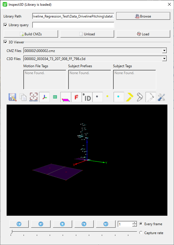
CMO Library Path
The CMO Library Path section allows the user to select and load the CMO Library that they wish to use.
Library Path The dialogue box shows the folder path to the files that you are using.
Browse The browse button allows the user to open the standard select folder dialogue which allows you to select the files that you wish to use.
Library Query The query library dialogue box allows the user to query only a portion of their library.
Build CMZs The build CMZs button allows the user to combine C3D files into one CMZ that can be loaded into Inspect3D.
Load The load button allows the user to load the CMZ workspace into Inspect3D.
Unload The unload button allows the user to remove the files that they have loaded into Inspect3D.
Library Files
Files
The CMO file drop down menu has a list of all the .cmo files that are loaded into Inspect3D.
The Tag drop down menu allows the user to see the tags that are associated with the CMO file that is selected in the CMO file drop down menu.
The C3D File list has the file names of all the .c3d files in the .cmo file that is selected in the CMO File Drop Down menu.
Animation Window

Save 3D-View This button allows you to save what is currently being displayed in the 3D view graphics area. The image can be saved in a number of standard formats, such as .bmp, .ico, .jpeg, .jpg, .pbm, .pgm, .png, .ppm, .tif, .tiff, .wbmp, .xbm, or .xpm. This function is ideal for producing graphics for papers or presentations. Saved images can be edited with 3rd party graphics programs if needed.

Copy 3D-View to Clipboard This button allows you to copy what is currently being displayed in the 3D view graphics area to the clipboard. This allows you to paste the image into any program that supports copy and paste. This is useful for working with presentation or graphics editing software.

Reset Camera This button brings the 3D viewer back to it's beginning position. You may find that having used the rotation, translation, and zooming capabilities of the 3D view you have lost track of where you are in the graphics, which can make returning to a proper view of your data challenging. The reset view button removes this frustration and reorients you.

Floor This button adds/removes the floor in the 3D-view.

Axis This button adds/removes an axis in the 3D-view.

Marker Labels This button adds/removes marker labels for each marker in the 3D-view.

Force Plates This button adds/removes force plates in the 3D-view.

Force Vectors This button adds/removes force vectors in the 3D-view as measures by the force platforms in the c3d file.

Target Markers This button adds/removes the target markers that were recorded by the motion capture system.

Segment Markers This button adds/removes markers for any segments that have been created in the .cmo file.

Segment Lines This button adds/removes lines for any segments that have been created in the .cmo file.

Segment Geometry This button adds/removes geometrical shapes to represent any segments that have been created in the .cmo file.

Segment Bones This button adds/removes bones to segments that have been created in the .cmo file.

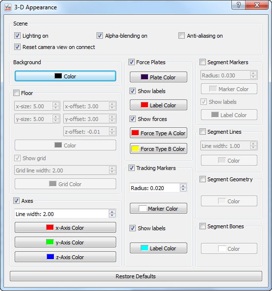
3D View Preferences This button allows you to change how the graphics that are presented to you. Changes happen in real time. At the bottom is the "Restore Defaults" button which resets all of the options to their standard setting.
Scene

|
Lighting on - When selected graphics that are suppose to be 3 dimensional have shadows to help simulate shape. When not selected objects are one solid color.
Reset camera view on connect - When this box is selected and you connect or reconnect to hardware the camera view will reset to it's default.
Alpha-blending on - When this box is selected the graphics are slightly transparent and allow you to see what is behind them
Anti-ailiasing on - When this box is selected all the lines in the graphics are smooth. If it is not selected the lines that are not either horizontal or vertical change directions portion by portion.
Background
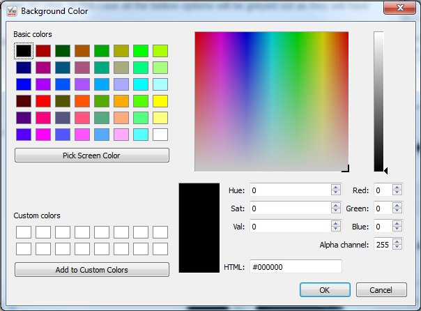
Color - This allows you to change the background color to anyone you chose.
Floor
When the check box next to the floor is not checked the floor will not appear in the 3D View. In this case all the bellow options will be greyed out as they will have no effect if the floor is not present.
X-size - This allows you to customize how many panels the floor is composed of in the x direction. the minimum is 1 and maximum is 100. The default size is 5.00.
Y-size - This allows you to customize how many panels the floor is composed of in the y direction. the minimum is 1 and maximum is 100. The default size is 5.00.
X-offset - This allows you to shift the entire floor along the x-axis either in the positive or negative direction. The maximum value allowed is 100 and the minimum value is -100. The default setting is 3.00.
Y-offset - This allows you to shift the entire floor along the y-axis either in the positive or negative direction. The maximum value allowed is 100 and the minimum value is -100. The default setting is 3.00.
Z-offset - This allows you to shift the entire floor along the z-axis either in the positive or negative direction. The maximum value allowed is 100 and the minimum value is -100. The default setting is -0.01.
Color - This allows you to change the floor color to anyone you chose.
Show grid - This allows you to remove the grid lines from the floor by unchecking the checkbox.
Grid line width - This allows you to change the thickness of the gridlines. The minimum value is 1 and the maximum value is 10. The default width is 2.00.
Grid color - This allows you to change the grid line color to anyone you chose.
Axes
When the check box next to the axis is not checked the axis will not appear in the 3D View. In this case all the bellow options will be greyed out as they will have no effect if the axis is not present.
Line width - This allows you to change the thickness of the axis lines. The minimum value is 1 and the maximum value is 10. The default value is 2.00.
X-Axis Color - This allows you to change the x-axis line color to anyone you chose.
Y-Axis Color - This allows you to change the y-axis line color to anyone you chose.
Z-Axis Color - This allows you to change the z-axis line color to anyone you chose.
Force Plates
When the check box next to the force plates is not checked the force plates will not appear in the 3D View. In this case all the bellow options will be greyed out as they will have no effect if the force plates are not present.
Plate Color - This allows you to change the force plate color to anyone you chose.
Show labels - This allows you to remove the force plate label, (such as FP1, FP2 . . . etc) from the 3D view.
Label Color - This allows you to change the force plate label color to anyone you chose.
Show forces - When checked the forces will be show in the 3D view using arrows.
Force Type A Color - This allows you to change the color of the raw force arrows to anyone you chose.
Force Type B Color - This allows you to change the color of the force structure arrows to anyone you chose.
Tracking Markers
When the check box next to the tracking markers is not checked the tracking markers will not appear in the 3D View. In this case all the bellow options will be greyed out as they will have no effect if the tracking markers are not present.
Radius - This allows you to change the radius of the markers. The maximum value is 0.100 the minimum value is 0.001. The default radius is 0.020.
Marker Color - This allows you to change the color of the marker color to anyone you chose.
Show Labels - This allows you to remove the marker labels from the 3D view.
Label Color - This allows you to change the color of the label to anyone you chose.
Segment Markers

|
When the check box next to the segment markers is not checked the segment markers will not appear in the 3D View. In this case all the bellow options will be greyed out as they will have no effect if the segment markers are not present.
Radius - This allows you to change the radius of the markers. The maximum value is 0.100 the minimum value is 0.001. The default radius is 0.020.
Marker Color - This allows you to change the color of the marker color to anyone you chose.
Show Labels - This allows you to remove the marker labels from the 3D view.
Label Color - This allows you to change the color of the label to anyone you chose.
Segment Lines
When the check box next to the segment lines is not checked the segment lines will not appear in the 3D View. In this case all the bellow options will be greyed out as they will have no effect if the segment lines are not present.
Line Width - This allows you to change the thickness of the segment lines. The minimum value is 1 and the maximum value is 10. The default value is 1.00.
Color - This allows you to change the color of the segment lines to anyone you chose.
Segment Geometry
When the check box next to the segment geometry is not checked the segment geometry will not appear in the 3D View. In this case all the bellow options will be greyed out as they will have no effect if the segment geometry is not present.
Color - This allows you to change the color of the segment geometry to anyone you chose.
Segment Bones
When the check box next to the segment bones is not checked the segment bones will not appear in the 3D View. In this case all the bellow options will be greyed out as they will have no effect if the segment bones are not present.
Color - This allows you to change the color of the segment bones to anyone you chose.
3D-Viewer - When a file is selected there will be a 3D-view of the data in the c3d file. The buttons below the viewer allows the user to navigate the c3d file. The buttons are, from left to right, Move to beginning, Move one back, Start/Pause, Move one forward, and Move to end. To the far right of the buttons is a counter, which indicates the frame number, as well as the radio buttons that allow the user to set the speed of the c3d file to either Every Fame or Capture Rate. The slider bar below the buttons indicates where in the c3d file the viewer is. It can be dragged back and forth to navigate the file.
