Lowpass Filter
| Language: | English • français • italiano • português • español |
|---|
Lowpass filter the points of a signal using a bidirectional filter.
The user can specify a BUTTERWORTH or CRITICALLY_DAMPED filter.
Visual3D uses a Butterworth Bidirectional Filter for Lowpass/Highpass filtering. The number of bidirectional passes specified determines the order of the filter (e.g. 1 bidirectional pass results in a fourth order filter). This means if the NUM_BIDIRECTIONAL_PASSES parameter is set to 1, the filter is a fourth order, if the NUM_BIDIRECTIONAL_PASSES is set to two, the filter is an eighth order filter.
The cutoff frequency takes into account the number of bidirectional passes through the signal.
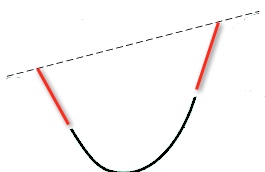
For the lowpass filter the slope of the signal is removed before filtering the data, then replaced after filtering.
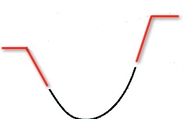
Digital filters do not work particularly well at the ends of the data array. In an attempt to minimize this problem, the procedure used in Visual3D is to buffer the data at both ends. The user can specify that the data be reflected at the beginning and end of the array and/or that the data be linearly extrapolated at the beginning and end of the array. For example, if 10 points are reflected and the total size of the buffer is set to 20, 10 points will be reflected at the beginning and end of the signal, the 10 additional frames of data will be extrapolated linearly.
After the data is filtered, the buffer is deleted.
Num_Reflected_Frames
Filters are not particularly effective near the ends of the signal, so it is often useful to add an artificial buffer.
Frames can be reflected about the endpoints.
Num_Extrapolate_Frames
Num_Buffered_Frames
The signal can be buffered beyond the reflection or extrapolation.
Maximum Cutoff Frequency
The default lowpass filter in Visual3D is a fourth order butterworth filter.
Butterworth filters have an upper limit on the magnitude of the cutoff frequency.
The maximum theoretical cutoff frequency is (sampling_rate*0.802/2).
VIsual3D is a little more conservative than that because we have found the filter to be unreliable at the theoretical limits.
The highest cutoff frequency that VIsual3D will allow you is 0.393* sampling-rate.
If your EMG signals are sampled at 1000 Hz, the highest cutoff frequency is 393 Hz.
Note that the cutoff frequency can be specified as an expression.
For example, consider that the signal to be filtered is an ANALOG signal.
/Frequency_Cutoff= 0.393*METRIC::PROCESSED::ANALOG_RATE
Pipeline Command
- Lowpass_Filter
- /Signal_Types= The type of signal to be processed
- /Signal_Names= The names of the signals to be processed
- /Signal_Folder= The name of the signal folder
- /Result_Types= The type of the resulting signal
- /Result_Names= The name of the resulting signals
- /Result_Folder= The data tree folder that the resulting signal is placed.
- /Result_Suffix= A suffix that can be applied to the original signal name
- /Filter_Class= BUTTERWORTH or CRITICALLY_DAMPED
- /Frequency_Cutoff= The window containing the frames to be averaged.
- /Num_Reflected= The number of points reflected at the ends of the signal
- /Num_Extrapolated= The number of points added based on a linear extrapolation
- /Total_Buffer_Size= Total size of the addition buffer (includes reflected points)
- /Num_Bidirectional_Passes= Number of Bidirectional passes through the data
- ;
NOTE: The procedure filters the input data from the first good frame of data to the last good frame of data.
The leading and trailing data (POINT Reliability - fourth component of the POINT signal in the data tree) are ignored.
Example
Explore the changes to the kinematics (e.g. LINK_MODEL_BASED signals) caused by changes to the cutoff frequency.
In this example:
- five cutoff filters (5, 6, 7, 8, and 9 Hz) are applied.
- The LINK_MODEL_BASED signals are updated
- the LINK_MODEL_BASED signals are copied to a unique folder
- For_Each
- /ITERATION_PARAMETER_NAME=CUTOFF
- /ITEMS=5+6+7+8+9
- ;
- Lowpass_Filter
- /SIGNAL_TYPES=TARGET
- ! /SIGNAL_NAMES=
- ! /SIGNAL_FOLDER=ORIGINAL
- ! /RESULT_SUFFIX=
- ! /RESULT_FOLDER=PROCESSED
- ! /FILTER_CLASS=BUTTERWORTH
- /FREQUENCY_CUTOFF=::CUTOFF
- ! /NUM_REFLECTED=6
- ! /TOTAL_BUFFER_SIZE=6
- ! /NUM_BIDIRECTIONAL_PASSES=1
- ;
- Recalc
- ;
- Copy_Folder
- /SIGNAL_TYPE=LINK_MODEL_BASED
- /EXISTING_FOLDER=ORIGINAL
- /NEW_FOLDER_NAME=CUTOFF&::CUTOFF
- /OVERWRITE_EXISTING_SIGNALS=TRUE
- ;
- End_For_Each
- /ITERATION_PARAMETER_NAME=CUTOFF
- ;
Reference
Robertson DGE and Dowling JJ (2003) Design and responses of Butterworth and critically dampted digital filters. Journal of Electromyography and Kinesiology 13. 569-573


