Marker Set Guidelines
| Language: | English • français • italiano • português • español |
|---|
The following image displays a frontal image of a conservative full body marker set, but there are many reasons why it might be necessary to modify this marker set. This topic provides a set of possibilities.
In most cases, there are more than one common definition of a segment, so we have mentioned multiple possibilities.
Marker Naming Convention
Marker names are derived from:
Marker Color Convention
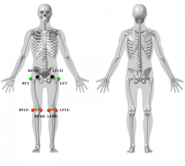
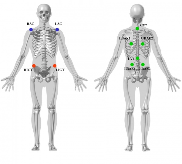
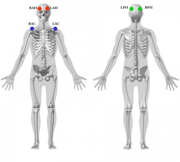
The different colored circles relate to the different roles of the markers.
- Red Markers are used for both the segment definition and for tracking
- Green Markers are used for tracking only
- Blue markers are used only for the segment definitions (these can be removed for the movement trial)
- Black markers are virtual markers used for both the segment definition and for tracking
Pelvis Segment
Visual3D Pelvis
- RFT , LFT= Femur greater Trochanter [1]:p. 114
- RICT, LICT= Ilium Crest Tubercle (Iliac Crest) [1]:p. 112
- RIPS , LIPS= Ilium Posterior Superior (Posterior Superior Iliac Spine) [1]:p. 107
Coda_Pelvis
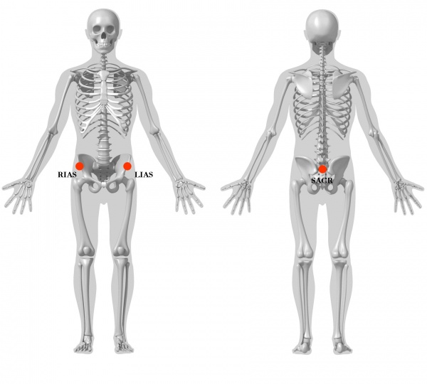
- RIAS , LIAS= Ilium Anterior Superior (Anterior Superior Iliac Spine) [1]:p. 106
- RIPS , LIPS= Ilium Posterior Superior (Posterior Superior Iliac Spine) [1]:p. 107
Helen Hayes Pelvis
- RIAS , LIAS= Ilium Anterior Superior (Anterior Superior Iliac Spine) [1]:p. 106
- SACR = Sacrum (Mid-point between RIPS and LIPS)
Thigh Segment
Visual3D treats the thigh as a geometrical primitive (conical frustrum)
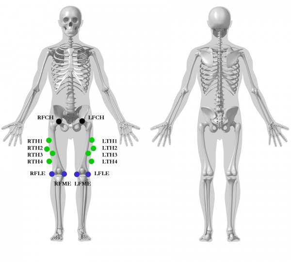
The proximal radius is the geometrical radius of the proximal end of the thigh. You can use calipers to measure this or you can approximate this measure as one quarter of the distance between the greater trochanters.
Thigh Model 1
- RFT , LFT= Femur greater Trochanter [1]:p. 114
- RFLE, LFLE=Femur Lateral Epicondyle [1]:p. 122
- RFME, LFME=Femur Medial Epicondyle [1]:p. 120
Thigh Model 2
- RFCH, LFCH=Femur Center of Head [1]:p. 132
- RFLE, LFLE=Femur Lateral Epicondyle [1]:p. 122
- RFME, LFME=Femur Medial Epicondyle [1]:p. 120
Thigh Model 3
- RFT , LFT= Femur greater Trochanter [1]:p. 114
- RFCH, LFCH=Femur Center of Head [1]:p. 132
- RFLE, LFLE=Femur Lateral Epicondyle [1]:p. 120
- RFME, LFME=Femur Medial Epicondyle [1]:p. 120
Thigh Model 4
- RFCH, LFCH=Femur Center of Head [1]:p. 132
- RFLE, LFLE=Femur Lateral Epicondyle [1]:p. 122
- RFME, LFME=Femur Medial Epicondyle [1]:p. 120
Shank Segment
Consistent with our recommendation for the thigh, we recommend that users avoid the lateral knee marker as a tracking marker unless the medial knee marker is also a tracking marker.
Shank Model 1
- RFLE, LFLE=Femur Lateral Epicondyle [1]:p. 122
- RFME, LFME=Femur Medial Epicondyle [1]:p. 120
- RFAL, LFAL=Fibula Apex of Lateral Malleolus [1]:p. 158
- RTAM, LTAM= Tibia Apex of Medial Malleolus [1]:p. 148
Shank Model 2
- RFLE, LFLE=Femur Lateral Epicondyle [1]:p. 122
- RFME, LFME=Femur Medial Epicondyle [1]:p. 120
- RFAL, LFAL=Fibula Apex of Lateral Malleolus [1]:p. 158
- RTAM, LTAM= Tibia Apex of Medial Malleolus [1]:p. 148
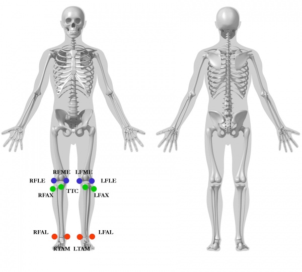
Shank Model 3
- RFLE, LFLE=Femur Lateral Epicondyle [1]:p. 122
- RFME, LFME=Femur Medial Epicondyle [1]:p. 120
- RFAL, LFAL=Fibula Apex of Lateral Malleolus [1]:p. 158
- RTAM, LTAM= Tibia Apex of Medial Malleolus [1]:p. 148
- RFAX, LFAX= Apex of the Styloid Process, head of Tibia [1]:p. 154
- TTC= Right and Left Tibial Tuberosity [1]:p. 144
Shank Model 4
- RFLE, LFLE=Femur Lateral Epicondyle [1]:p. 120
- RFME, LFME=Femur Medial Epicondyle [1]:p. 120
- RFAL, LFAL=Fibula Apex of Lateral Malleolus [1]:p. 158
- RTAM, LTAM= Tibia Apex of Medial Malleolus [1]:p. 148
- RTTC,LTTC= Tibial Tuberosity [1]:p. 144
Foot Segment
One Segment Foot
This model is consistent with a one segment foot segment.
One segment foot with additional markers.
Multi-Segment Foot (Leardini)
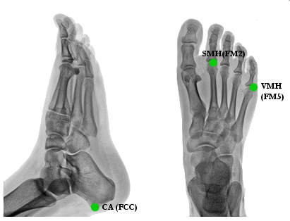
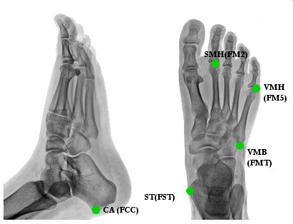
- CA[2](FCC) [1]:p. 160 = Posterior Surface of Calcaneus
- ST[2](FST)[1]:p. 160 = Sustentaculum Tali of Calcaneus
- SMH[2](FM2)[1]:p. 160 = Head of 2nd Metatarsus
- VMH[2](FM5)[1]:p. 160 = Head of 5th Metatarsus
- VMB[2](FMT)[1]:p. 160 = Tuberosity of 5th Metatarsal
- PM[2](PM6)[1]:p. 160 = Proximal Medial Phalanx
- FMB[2] = Base of First Metatarsal
- SMB[2] = Base of Second Metatarsal
Thorax/Ab Segment
Thorax/Ab Model 1
This marker set is consistent with both a one segment torso (Iliac Crest to Acromium) and a two segment torso; lumbar segment from Iliac Crest to a projection of the T10 (or T12) marker onto a plane defined by the Iliac Crest and Acromium; thoracic segment from the projected T10 marker to the acromium.
Thorax/Ab Model 2
Thorax/Ab Model 3
Thorax Segment
This marker set is consistent with the ISB recommendations.
A segment coordinate system consistent with the ISB recommendations is as follows:
- Landmark SJN_CV7
- Starting Point SJN
- Ending Point CV7
- Axial 0.5
- Offset by Percent
- Calibration Only
- Landmark SXS_MAI
- Starting Point SXS
- Ending Point MAI
- Axial 0.5
- Offset by Percent
- Calibration Only
- Segment THORAX
- Proximal Joint SJN_CV7
- Proximal Radius 0.5*DISTANCE(RAC,LAC)
- Distal Joint SXS_MAI
- Distal Radius 0.5*DISTANCE(RAC,LAC)
- Anterior Direction SJN
- Tracking Markers
- SJN
- CV7
- SXS
- MAI
Upper Arm and Lower Arm Segment
The upper arm segment is defined from the head of the humerus (shoulder "joint") to the elbow.
In this example, the orientation of the upper arm is determined by the placement of the medial and lateral elbow markers. It is quite difficult to place the medial marker, so we often recommend a standing posture in which the elbows are flexed at 90 degrees and the frontal plane of the upper arm is determined by the axial axis of the forearm.
The forearm segment is defined from the elbow joint (e.g. distal end of the upper arm segment) and the medial and lateral wrist markers assuming that the wrist markers are placed laterally on the wrist; if the wrist markers are placed on the posterior surface, it is necessary to create landmarks that are projected. It is often convenient to use a digitizing pointer to identify these locations. Note that supination/pronation of the forearm causes the medial and lateral elbow landmarks to NOT lie in the frontal plane of the forearm, so they should not be used as the proximal medial and lateral markers for the forearm.
Recommended Posture for the static trial
Defining the segment coordinate system for the humerus is particularly difficult because there are no bony landmarks to assist in determining the glenohumeral joint center, and medial and lateral markers on the epicondyles are close together and often do not represent the axis of rotation of the elbow.
The following explanation is personal opinion and users should not accept this as a recommendation, rather as one plausible approach. Further work needs to be done in this area and users must decide for themselves.
The upper arms should be placed in the anatomical position, so as to minimize the movement of the scapula relative to the thorax.
The head of the humerus can be estimated by placing 3 markers (one anterior, one posterior, and one lateral) on the surface. Create a landmark by projecting the lateral marker on to a line defined by the anterior and posterior marker. It is a bit of a nuisance to place 3 markers at the shoulder, but the equivalent locations can be identified using a digitizing pointer.
Static markers should be placed medial and lateral on the epicondyles of the elbow. The distal end of the humerus should lie at the midpoint of these two markers.
Now that the proximal and distal ends of the humerus are defined, the orientation of the humerus must be defined. A recommendation by the International Shoulder Group (ISG)is to have the forearm flexed to 90 degrees elbow flexion during the static trial, and use the long axis of the forearm to specify the anterior direction of the humerus. The palms of the hand should face the floor.
Note that this is different than the approach that was recommended by C-Motion prior to Visual3D version 3.25, in which we recommended that the upper arm and forearm be in the anatomical position.
Markers should be placed on the most caudal-lateral point on the radial styloid (RS) and the most caudal-medial point on the ulnar styloid (US). The distal end of the forearm can be placed at the midpoint of these two markers, or as per the ISG recommendation at the US.
The long axis of the forearm is defined from the midpoint of the epicondyles (e.g. the distal end of the humerus segment) and the distal end of the forearm.
The radius value for the proximal end of the upper arm is half the diameter of the upper arm at the level of the head of the humerus. The radius value for the distal end of the upper amr is half the diameter of the upper arm at the level of the elbow.
There are two problem with using this anatomical position:
- It is challenging to place the medial marker well, which results in unwanted axial rotation of the humerus coordinate system.
- Many subjects have a "carry angle" at the elbow, which increases the challenge of identifying the flexion/extension axis.
Model 1
In this model, there are 3 markers surrounding the head of the humerus. The origin of the upper arm is the projection of the lateral shoulder marker onto an axis passing through the anterior and posterior shoulder markers.
- RHLT, LHLT= Humerus Lesser Tubercle [1]:p. 65
- RHGT, LHGT= Humerus Greater Tubercle [1]:p. 64
- RSHO, LSHO= Shoulders
- RHLE, LHLE= Lateral Epicondyle of Humerus [1]:p. 68
- RHME, LHME= Medial Epicondyle of Humerus [1]:p. 67
- RHNT, LHNT= Navicular Tuberle [1]:p. 94
- RRSP, LRSP=Radius-Styloid Process [1]:p. 83
- RUSP, LUSP=Ulna-Styloid Process [1]:p. 77
- RHL, LHL, RHM, LHM= Lateral and Medial Head of Metacarpal [1]:p. 96
Model 2
In this model the origin of the upper arm is an offset from the acromion marker.
- RSHO, LSHO= Shoulders
- RHLE, LHLE= Lateral Epicondyle of Humerus [1]:p. 68
- RHME, LHME= Medial Epicondyle of Humerus [1]:p. 67
- RHNT, LHNT= Navicular Tuberle [1]:p. 94
- RRSP, LRSP=Radius-Styloid Process [1]:p. 83
- RUSP, LUSP=Ulna-Styloid Process [1]:p. 77
- RHL, LHL, RHM, LHM= Lateral and Medial Head of Metacarpal [1]:p. 96
- RSAJ, LSAJ=Scapula- Acromioclavicular Joint [1]:p. 60
Head Segment
If the purpose of the head segment is for kinematics only, the following definition is easy to use. The proximal end of the head is at the acromium and the distal end is vertically above the acromium at the level of the ear.
References
- ↑ 1.00 1.01 1.02 1.03 1.04 1.05 1.06 1.07 1.08 1.09 1.10 1.11 1.12 1.13 1.14 1.15 1.16 1.17 1.18 1.19 1.20 1.21 1.22 1.23 1.24 1.25 1.26 1.27 1.28 1.29 1.30 1.31 1.32 1.33 1.34 1.35 1.36 1.37 1.38 1.39 1.40 1.41 1.42 1.43 1.44 1.45 1.46 1.47 1.48 1.49 1.50 1.51 1.52 1.53 1.54 1.55 1.56 1.57 1.58 1.59 1.60 1.61 1.62 1.63 1.64 1.65 Serge van Sint Jan "Color Atlas of Skeletal Landmark Definitions: Guidelines for Reproducible Manual and Virtual Palpations" 2007 - Churchill Livingstone
- ↑ 2.0 2.1 2.2 2.3 2.4 2.5 2.6 2.7 Leardini, A., M.G. Benedetti, L. Berti, D. Bettinelli, R. Nativo, and S. Giannini. "Rear-foot, Mid-foot and Fore-foot Motion during the Stance Phase of Gait." Gait & Posture 25 (2007): 453-55


