Introduction
This tutorial explains how to implement OptiTracks Biomech (57) full body marker set[1]. This full body marker set includes the head, torso, upper and lower body, hands and feet.
The naming convention used in this tutorial follows Serge Van Sint Jan's convention[2].
Target Placement

LAH/RAH: Left/Right anterior head
LPH/RPH: Left/Right posterior head
SJN (IJ): Deepest point of incisura jugularis
SXS (PX): Xiphoid process, i.e. most caudal point of the sternum
CV7 (C7): Spinous process of the seventh cervical vertebrae
TV2 (T2): Second thoracic vertebrae
TV7 (MAI): Midpoint between the inferior angles of the most caudal points of the two scapulae
LHGT/RHGT: Left/Right glenohumeral Joint
LIAS/RIAS (LASIS/RASIS): Left/Right anterior superior iliac spine
LIPS/RIPS (LPSIS/RPSIS): Left/Right posterior superior iliac spine
LCAJ/RCAJ (LA/RA): Left/Right acromion
LHLE/RHLE: Left/Right humerus lateral epicondyle
LHME/RHME: Left/Right medial lateral epicondyle
LUA/RUA: Left/Right upper arm
LHM2/RHM: Left/Right hand second metatarsal
LUSP/RUSP: Left/Right ulna styloid process
LRSP/RRSP: Left/Right radius styloid process
LFTC/RFTC (LGT/RGT): Most lateral prominence of the greater trochanter
LFLE/RFLE (LLE/RLE): Most lateral prominence of the lateral femoral epicondyle
LFME/RFME (LME/RME): Most medial prominence of the medial femoral epicondyle
LTH/FTH: Left/Right thigh
LSK/RSK: Left/Right Superior knee
LTTC/RTTC (TT/RTT): Most anterior border of the tibial tuberosity
LFAX/RFAX (LHF/RHF): Proximal tip of the head of the fibula
LFAL/RFAL (LLM/RLM): Lateral prominence of the lateral malleolus
LTAM/RTAM (LMM/RMM): Most medial prominence of the medial malleolus
LFM5/RFM5 (LVM/RVM): Dorsal margin of the fifth metatarsal head
LFM1/RFM1 (LFM/RFM): Dorsal margin of the first metatarsal head
LFM2/RFM2 (LSM/RSM): Dorsal aspect of the second metatarsal head
LFCC/RFCC (LCA/RCA): Aspect of the achilles tendon insertion on the calcaneous
LDP1/RDP1: Left/Right distal phalanx
Segment Definition
Head Segment
Head Landmarks
|
1. Create Head_Front:
- Click Landmarks button
- Click Add New Landmark button
- Create Landmark: Head_Front
|
Landmark Name: Head_Front
Define Orientation Using:
Starting Point: RAH
Ending Point LAH
|
|
- Offset Using the Following AXIAL Offset: 0.5
- Check: Offset by Percent (1.0 = 100%)
- Check: Calibration Only Landmark
|
|
|
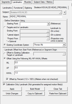
2. Create HEAD_PROXIMAL:
- Click Landmarks button
- Click Add New Landmark button
- Create Landmark: HEAD_PROXIMAL
|
Landmark Name: HEAD_PROXIMAL
Define Orientation Using:
Existing Coordinate System: Thorax/Ab
|
|
- Offset Using the Following AXIAL Offset: 1
- Check: Offset by Percent (1.0 = 100%)
- Check: Calibration Only Landmark
|
|
|
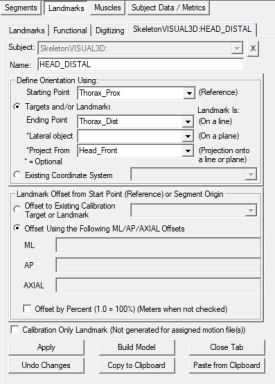
3. Create HEAD_DISTAL:
- Click Landmarks button
- Click Add New Landmark button
- Create Landmark: HEAD_DISTAL
|
Landmark Name: HEAD_DISTAL
Define Orientation Using:
Starting Point: Thorax_Prox
Ending Point Thorax_Dist
*Project From Head_Front
|
|
- Do NOT Check: Offset by Percent (1.0 = 100%)
- Do NOT Check: Calibration Only Landmark
|
|
Head Definition
|
1. Create Head:
- In the Segments tab, select Head in the Segment Name box.
- Click on the Create Segment button.
- In the Head tab, enter these values:
|
Define Proximal Joint and Radius
Lateral: None Joint: HEAD_PROXIMAL Medial: None
Radius: 0.5*DISTANCE(RAH,LAH)
Define Distal Joint and Radius
Lateral: none Joint: HEAD_DISTAL Medial: none
Radius: 0.5*DISTANCE(RPH,LPH)
Extra Target to Define Orientation: Posterior, Head_Front
Select Tracking Targets:
LAH, LPH, RAH, RPH
|
|
- Click on Build Model.
- Click on Close Tab before proceeding.
|
|
Thorax Segment
Thorax Landmarks
|
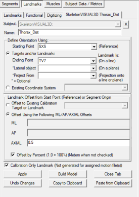
1. Create Thorax_Dist:
- Click Landmarks button
- Click Add New Landmark button
- Create Landmark: Thorax_Dist
|
Landmark Name: Thorax_Dist
Define Orientation Using:
Starting Point: SXS
Ending Point TV7
|
|
- Offset Using the Following AXIAL Offset: 0.5
- Check: Offset by Percent (1.0 = 100%)
- Check: Calibration Only Landmark
|
|
|
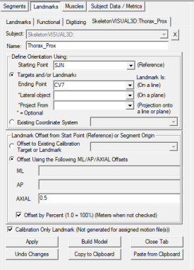
2. Create Thorax_Prox:
- Click Landmarks button
- Click Add New Landmark button
- Create Landmark: Thorax_Prox
|
Landmark Name: Thorax_Prox
Define Orientation Using:
Starting Point: SJN
Ending Point CV7
|
|
- Offset Using the Following AXIAL Offset: 0.5
- Check: Offset by Percent (1.0 = 100%)
- Check: Calibration Only Landmark
|
|
|
3. Create Thorax_AP:
- Click Landmarks button
- Click Add New Landmark button
- Create Landmark: Thorax_AP
|
Landmark Name: Thorax_AP
Define Orientation Using:
Starting Point: SJN
Ending Point SXS
|
|
- Offset Using the Following AXIAL Offset: 0.5
- Check: Offset by Percent (1.0 = 100%)
- Check: Calibration Only Landmark
|

|
Thorax Definition
|
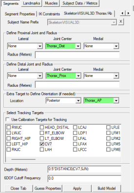
1. Create Thorax/Ab:
- In the Segments tab, select Thorax/Ab in the Segment Name box.
- Click on the Create Segment button.
- In the Thorax/Ab tab, enter these values:
|
Define Proximal Joint and Radius
Lateral: None Joint: Thorax_Dist Medial: None
Radius: 0.5*DISTANCE(RCAJ,LCAJ)
Define Distal Joint and Radius
Lateral: none Joint: Thorax_Prox Medial: none
Radius: 0.5*DISTANCE(RCAJ,LCAJ)
Extra Target to Define Orientation: Posterior, Thorax_AP
Select Tracking Targets:
CV7, SJN, SXS, TV7
Depth: 0.5*DISTANCE(CV7,SJN)
|
|
- Click on Build Model.
- Click on Close Tab before proceeding.
|
|
Upper Arm Segment
Upper Arm Landmarks
|
1. Create LSJC Joint Center:
- Click Landmarks button
- Click Add New Landmark button
- Create Landmark: LSJC
|
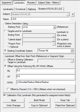
Landmark Name: LSJC
Define Orientation Using:
Starting Point: LCAJ
Exisiting Coordinate System: Thorax/Ab
|
|
- Offset Using the Following AXIAL Offset: -(LShoulderRadius+MarkerRadius)
- Do NOT Check: Offset by Percent (1.0 = 100%)
- Check: Calibration Only Landmark
|
|
Upper Arm Definition
|
1. Create Left Forearm:
- In the Segments tab, select Left Upper Arm in the Segment Name box.
- Click on the Create Segment button.
- In the Upper arm tab, enter these values:
|
Define Proximal Joint and Radius
Lateral: None Joint: LSJC Medial: None
Radius: LShoulderRadius
Define Distal Joint and Radius
Lateral: LHLE Joint: None Medial: LHME
Select Tracking Targets:
LHLE, LHME, LUA,
|
|
- Click on Build Model.
- Click on Close Tab before proceeding.
|
|
Forearm Segment
Forearm Landmarks
|
1. Create LT_ELBOW Joint Center:
- Click Landmarks button
- Click Add New Landmark button
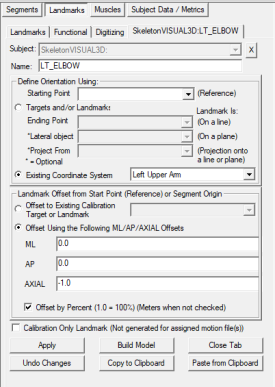
- Create Landmark: LT_ELBOW
|
Landmark Name: LT_ELBOW
Define Orientation Using:
Exisiting Coordinate System: Left Upper Arm
|
|
- Offset Using the Following AXIAL Offset: -1.0
- Check: Offset by Percent (1.0 = 100%)
- Do NOT Check: Calibration Only Landmark
|
|
Forearm Definition
|
1. Create Left Forearm:
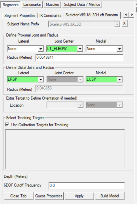
- In the Segments tab, select Left Forearm in the Segment Name box.
- Click on the Create Segment button.
- In the Left Forearm tab, enter these values:
|
Define Proximal Joint and Radius
Lateral: None Joint: LT_ELBOW Medial: None
Radius: 0.0548641
Define Distal Joint and Radius
Lateral: LRSP Joint: None Medial: LUSP
Select Tracking Targets:
Use Calibration Targets for Tracking
|
|
- Click on Build Model.
- Click on Close Tab before proceeding.
|
|
Hand Segment
Hand Landmarks
|
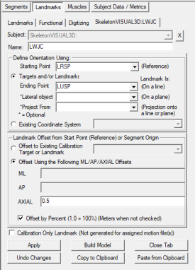
1. Create LWJC Joint Center
- Click Landmarks button
- Click Add New Landmark button
- Create Landmark: LWJC
|
Landmark Name: RANK
Define Orientation Using:
Starting Point: LRSP
Ending Point: LUSP
|
|
- Offset Using the Following ML/AP/AXIAL Offsets:
- X: 0.0 Y: 0.0 Z: 0.5
- Check: Offset by Percent (1.0 = 100%)
- Do NOT Check: Calibration Only Landmark
|
|
|
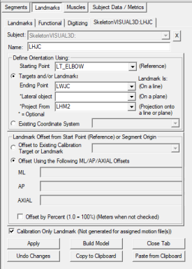
2. Create LHJC Joint Center
- Click Landmarks button
- Click Add New Landmark button
- Create Landmark: LHJC
|
Landmark Name: RANK
Define Orientation Using:
Starting Point: LT_ELBOW
Ending Point: LWJC
*Project From: LHM2
|
|
- Offset Using the Following ML/AP/AXIAL Offsets:
- X: 0.0 Y: 0.0 Z: 0.0
- Do NOT Check: Offset by Percent (1.0 = 100%)
- Check: Calibration Only Landmark
|
|
Hand Definition
|
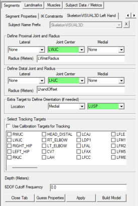
1. Create Left Hand:
- In the Segments tab, select Left Hand in the Segment Name box.
- Click on the Create Segment button.
- In the Left Hand tab, enter these values:
|
Define Proximal Joint and Radius
Lateral: None Joint: LWJC Medial: None
Radius: LWristRadius
Define Distal Joint and Radius
Lateral: none Joint: LHJC Medial: none
Select Tracking Targets:
LHM2, LRSP, LUSP
|
|
- Click on Build Model.
- Click on Close Tab before proceeding.
|
|
Pelvis Segment
Pelvis Definition
|
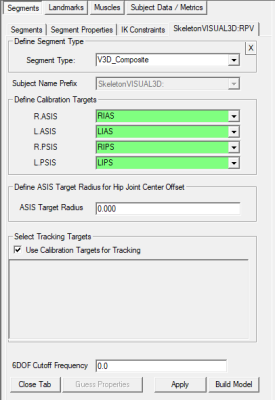
1. Create Pelvis Segment:
- In the Segments tab, select Pelvis in the Segment Name box.
- In Segment Type, select V3D_Composite
- Click on the Create Segment button.
- In the Pelvis dialog:
|
Define Calibration Targets
R.ASIS: RIAS
L.ASIS: LIAS
R.PSIS: RIPS
L.PSIS: LIPS
Check Use Calibration Targets for Tracking
|
|
- Click on Build Model.
- Click on Close Tab before proceeding.
|
|
Thigh Segment
Thigh Landmarks
|
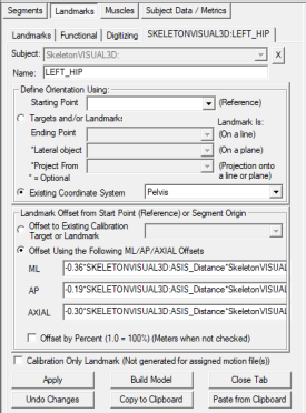
1. Create LEFT_HIP Joint Center:
- Click Landmarks button
- Click Add New Landmark button
- Create Landmark: LEFT_HIP
|
Landmark Name: LEFT_HIP
Define Orientation Using:
Existing Coordinate System Pelvis
|
|
- Landmark Offset from Start Point or Segment Origin
- ML: -0.36*ASIS_Distance*RPV_ML_Direction
- AP: 0.19*SASIS_Distance*RPV_AP_Direction+0.5*:RPV_Depth - Target_Radius_ASIS
- AXIAL: -0.30*ASIS_Distance*RPV_Axial_Direction
- Do NOT Check: Offset by Percent (1.0 = 100%)
- Do NOT Check: Calibration Only Landmark
|
|
Thigh Definition
|
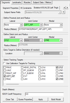
1. Create Left Thigh:
- In the Segments tab, select Left Thigh in the Segment Name box.
- Click on the Create Segment button.
- In the Left Thigh tab, enter these values:
|
Define Proximal Joint and Radius
Lateral: None Joint: LEFT_HIP Medial: None
Radius: 0.5*DISTANCE(RIGHT_HIP,LEFT_HIP)
Define Distal Joint and Radius
Lateral: LFLE Joint: None Medial: LFME
Select Tracking Targets:
LEFT_HIP, LFLE, LFME, LFTC, LTH
|
|
- Click on Build Model.
- Click on Close Tab before proceeding.
|
|
Shank Segment
Shank Definition
|
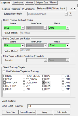
1. Create Left Shank:
- In the Segments tab, select Left Shank in the Segment Name box.
- Click on the Create Segment button.
- In the Left Shank tab, enter these values:
|
Define Proximal Joint and Radius
Lateral: LFLE Joint: none Medial: LFME
Define Distal Joint and Radius
Lateral: LFAL Joint: None Medial: LTAM
Select Tracking Targets:
LFAL, LFAX, LTAM, LTTC
|
|
- Click on Build Model.
- Click on Close Tab before proceeding.
|
|
|
1. Create Left Foot:
- In the Segments tab, select Left Foot in the Segment Name box.
- Click on the Create Segment button.
- In the Left Foot tab, enter these values:
|
Define Proximal Joint and Radius
Lateral: LFAL Joint: none Medial: LTAM
Define Distal Joint and Radius
Lateral: LFM5 Joint: None Medial: LFM1
Select Tracking Targets:
LDP1, LFCC, LFM1, LFM2, LFM5
|
|
- Click on Build Model.
- Click on Close Tab before proceeding.
|
|
References


